Display screen
A technology for display screens and display modules, applied in the field of display screens, can solve problems such as low efficiency, module damage, troublesome maintenance of LED display screens, etc., so as to improve efficiency, reduce the probability of damage, and solve the effects of low maintenance efficiency
- Summary
- Abstract
- Description
- Claims
- Application Information
AI Technical Summary
Problems solved by technology
Method used
Image

Examples
Embodiment 1
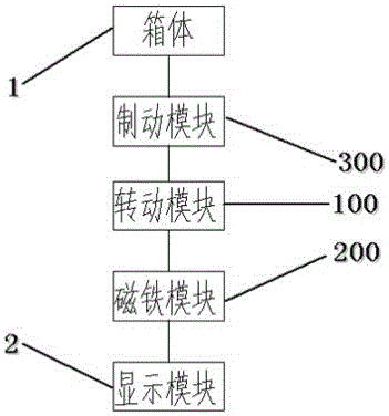
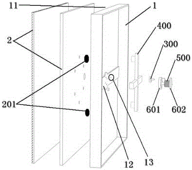
[0080] Such as figure 1 As shown, the display screen of Embodiment 1 includes a box body 1 , a display module 2 , a rotation module 100 , a magnet module 200 and a braking module 300 . An opening 11 is preset on the box body 1 , and the display module 2 is connected to the box body through the opening 11 . The magnet module 200 is composed of a magnetic pole group a201 and a magnetic pole group b202 , and the magnetic pole group a201 is arranged on the display module 2 . The braking module 300 controls the movement state of the rotating module 100. When the display device 2 does not need to be maintained, the braking module 300 maintains the original state. At this time, the rotating module 100 cannot rotate due to the restriction of the braking module 300; When the display device 2 needs to be maintained, the brake module 300 is artificially braked so that it no longer maintains the original state. At this time, because the rotating module 100 is no longer restricted by the ...
Embodiment 2
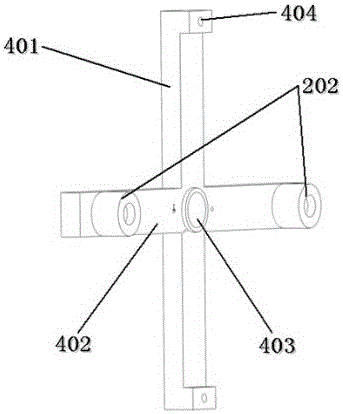
[0088] Such as figure 1 , Figure 5 , Image 6 with Figure 7 As shown, the difference between the display screen of the second embodiment and the first embodiment is that the rotating module 100 is a round table 700 . The round table 700 is rotatably fixed on the box body 1, and the center of the round table 700 is connected with the box body 1 to realize fixing. The round table is connected to the display module 2 through the two magnetic pole groups of the magnet group 200 , namely the magnetic pole group a201 and the magnetic pole group b202 . The magnetic pole group a201 is arranged on the display module 2 , and the magnetic pole group b202 is arranged on the disk 700 . The magnetic pole group a201 or the magnetic pole group b202 has two magnetic poles, an N pole and an S pole. When the display screen does not require maintenance, the N pole of the magnetic pole group a201 corresponds to the S pole of the magnetic pole group b202 or the S pole of the magnetic pole gr...
Embodiment 3
[0095] Such as figure 1 , Figure 8 with Figure 9 As shown, the display screen of this embodiment includes: a box body 1 , a display module 2 , a rotation module 100 , a magnet module 200 , a braking module 300 , a slider 1000 and a rope 1100 . An opening 11 is preset on the box body 1 , and the display module 2 is connected to the box body through the opening 11 . The display module 2 can be an LCD display component or an LED display module, preferably an LED display module. The magnet module 200 is composed of three parts, namely, the magnetic pole group 201 arranged on the display module 2, the magnetic pole group c203 arranged on the display module 2, and the magnetic pole group b202 arranged on the slider 1000, and the magnetic pole group a201 and the magnetic pole group c203 are set separately . The magnetic poles of the magnetic pole group a201 and the magnetic pole group b202 have the same polarity, and the magnetic poles of the magnetic pole group b202 and the ma...
PUM
 Abstract
Description
Claims
Application Information
 - R&D
- Intellectual Property
- Life Sciences
- Materials
- Tech Scout
- Unparalleled Data Quality
- Higher Quality Content
- 60% Fewer Hallucinations
Browse by: Latest US Patents, China's latest patents, Technical Efficacy Thesaurus, Application Domain, Technology Topic, Popular Technical Reports.
© 2025 PatSnap. All rights reserved.Legal|Privacy policy|Modern Slavery Act Transparency Statement|Sitemap|About US| Contact US: help@patsnap.com