Apparatus for producing and/or packaging products in the tobacco industry

A technology of products, devices, applied in the field of devices for the manufacture and/or packaging of products of the tobacco industry, to the effect of avoiding geometric distortions

Active Publication Date: 2016-12-14
FOCKE & CO (GMBH & CO KG)
9 Cites 6 Cited by

AI-Extracted Technical Summary

Problems solved by technology

However, it is difficult, for example, during the above-mentioned process of pushing the pack group into the folding turre...

Method used

[0055] Each mirror 38 or its reflecting mirror surface (as this is the case in the case of the elongated mirrors in the embodiments according to FIGS. 3 and 4 ) is inclined relative to the conveying plane. However, the mirror 38 or the mirror surface is not oriented perpendicularly to the conveying dir...

Abstract

The invention relates to an apparatus for producing and/or packaging products (13) in the tobacco industry, in particular for packaging cigarette packs (13) in multipacks (21), having a conveying mechanism (34) which can be moved preferably back and forth, for example a conveying mechanism which is intended for pushing or thrusting the products and by means of which at least in each case one product (13) can be conveyed, in particular pushed or thrust, in an in particular non-curved conveying plane, with at least temporary abutment against the conveying mechanism (34), from a first position into a second position. The invention is characterized by an electro-optical detecting device (32) which is oriented onto the side (36) of the product (13), the conveying mechanism (34) butting at least temporarily against said side - product-abutment side - and can detect the product-abutment side (36), in at least one movement state of the conveying mechanism (34), from the direction of the conveying mechanism (34).

Application Domain

Packaging cigarettePackaging cigars +1

Technology Topic

Cigarette packEngineering +3

Image

  • Apparatus for producing and/or packaging products in the tobacco industry
  • Apparatus for producing and/or packaging products in the tobacco industry
  • Apparatus for producing and/or packaging products in the tobacco industry

Examples

  • Experimental program(1)

Example Embodiment

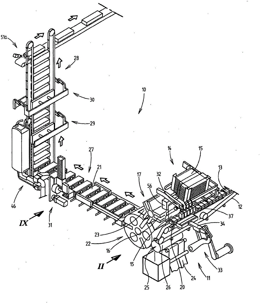
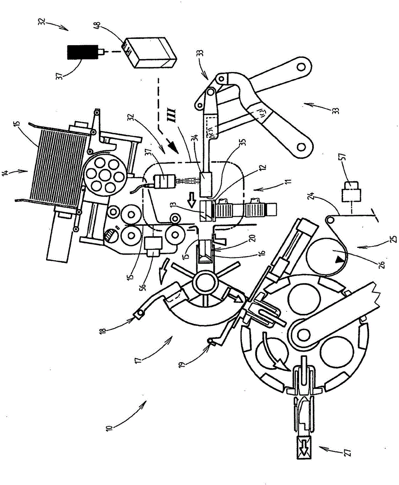
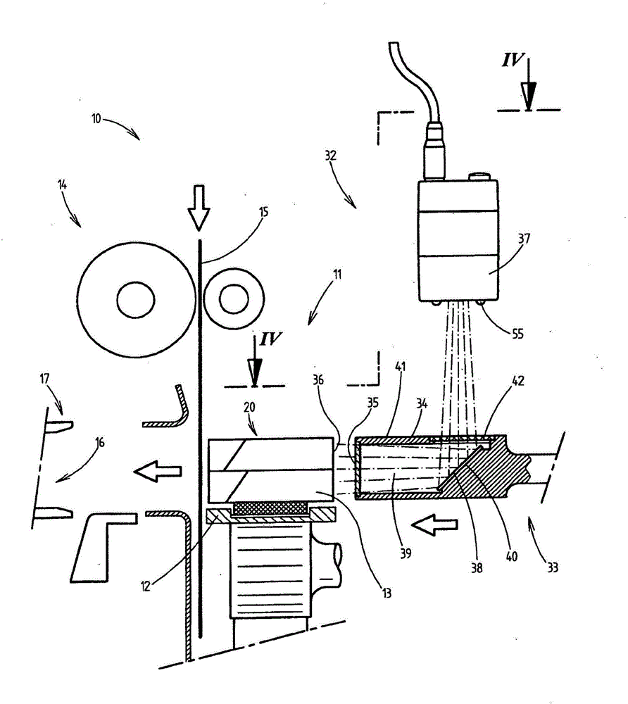
[0027] The embodiment of the invention described below relates to a so-called bale or strapping machine 10. However, the present invention is not limited to strapping machines, but can also be used in other different equipment for manufacturing and/or packaging products of the tobacco industry, such as carton packaging machines, packaging machines for manufacturing individual cigarette packs, etc.
[0028] Strapping machines have long been known in the prior art and are described, for example, in DE 10 2011 103 821 A1, the content of which is fully incorporated into the present application.
[0029] Here, such a strapping machine or said strapping machine 10 includes a push-in station 11 in which cigarette packs 13 grouped into a pack group 20 on a continuous conveyor 12 (currently endless belt) are periodically and sequentially The (cardboard) blanks 15 from the blanking mechanism 14 are pushed into each of the prepared pockets 16 of the folding turret 17 while driving.
[0030] Previously, production data, such as brand data, production date, equipment data, etc., were applied to the (cardboard) blank 15 by means of a printing device 56, for example a laser recorder.
[0031] Each packaging group 20 currently includes two stacked rows of multiple (currently five) packages 13 arranged side by side in the direction of the continuous conveyor 12. After the packaging group 20 is pushed into the prepared bag 16, the folding turret 17 further rotates until the next free turret bag 16 is at the height of the continuous conveyor 12 or in the area of ​​the push-in station 11, thereby The next packing group 20 can be pushed.
[0032] The folding elements 18, 19 then fold the blank 15 of the package group 20 in the bag 16 around the corresponding package group 20. The group 20 so wrapped in the (cardboard) blank 15 is then transferred to another folding turret 22, in the area of ​​which there are folded packages made of film or alternatively of paper (Cardboard) The outer envelope 23 of the blank 15.
[0033] Here, the individual blanks for the outer envelope 23 are separated from the continuous material web 24 by means of a separating mechanism 25 including a cutter roller 26 in this case.
[0034] As an alternative to the above-described application of production data to the (cardboard) blank 15 in the area of ​​the push-in station 11, the production data can also be applied to the outer envelope 23, in particular the continuous material web 24, by means of the printing device 57 on. This is especially true when the outer envelope 23 is not configured to be transparent, but is, for example, a paper envelope.
[0035] The bundled packages 21 leaving the other folding turret 22 are then transported along the current horizontal transport section 27 to another conveyor, the current vertical conveyor 28. A labeling mechanism 31 is provided along the transportation section 27, and the labeling mechanism sets labels for the strapping package 21.
[0036] Two shrinking stations 29, 30 are arranged along the vertical conveyor 28, and the outer envelope 23 made of film shrinks on these two shrinking stations.
[0037] Then the vertical conveyor 28 follows the (horizontal) exporter, which continues to transport the strapping packages 21, in particular to the subsequent, not shown carton packaging machine, which respectively packs a predetermined number of strapping packages 21 Pack them in a cardboard box.
[0038] In order to be able to generate an image record of the corresponding bundled package 21 of the packed cigarette package 13, the push-in station 11 is equipped with a special detection device 32 for photoelectrically detecting the cigarette package 13 or group 20. These image records can then be used, for example, to enable the traceability of the cigarette package contained in the bundled package 21 in the sense of "tracing" which is also described in an implicit manner later. However, independently of this, the detection device 32 may also be used for other testing or monitoring purposes.
[0039] The detection device 32 is a part of the device 33 for inputting or pushing the cigarette group 20 transversely to the continuous conveyor 12 into the prepared corresponding bag 16 of the folding turret 17, and more precisely, it is currently along the horizontal Conveying plane or in a horizontal conveying plane.
[0040] Here, the device 33 includes a conveying element 34, that is to say a slide, which is also currently reciprocating in a horizontal plane. Here, the side 35 of the conveying element 34 facing the package 13 or the packaging group 20 is the conveying side of the conveying element 34, which can move onto the packaging group 20 within the range of a push-in movement (forward movement), In contact with the packaging group and at least temporarily abutting on the packaging group, it is moved in the direction of the folding turret bag 16 and pushed into the folding turret bag.
[0041] After the packaging group 20 is pushed into the prepared bag 16, the folding turret 17 rotates until the next free bag 16 of the folding turret 17 is in the area of ​​the pushing station 11. In addition, the conveying element 34 moves in the opposite direction (backward movement) in the reverse movement to a retracted position in which the packaging group 20 immediately following on the continuous conveyor 12 can be conveyed/conveyed to Push into the area of ​​station 11. Then, the conveying element 34 transports the (next) packaging group 20 in the push-in area to the area of ​​the folding turret 17 in the push-in station 11 within the scope of the next conveying cycle with a new push-in motion. In the other bag 16 and then move back into the retracted position. The depicted process repeats periodically.
[0042] The photoelectric detection device 32 is constructed in a special way due to the constraints in the area of ​​the push-in station 11, so that it can optimally detect that the cigarette pack 13 of the corresponding pack 20 is in contact with the folding element 34 or is being pushed in. At least temporarily abut the side on the folding element during this period. In this application, the side is referred to as the abutting side. In the illustrated embodiment, this is the bottom side 36 of the cigarette pack 13. Of course, it is also within the scope of the present invention to point the other side of the cigarette package 13 as the abutment side 36 in the direction of the conveying element 34 and then use the detection device 32 for detection accordingly.
[0043] The detection device 32 is aligned with the abutment side 36 of the cigarette pack 13 and is more precisely oriented such that the abutment side 36 can be detected from the direction of the conveying element 34, that is to say substantially parallel to the conveying direction of the conveying element 34.
[0044] For this purpose, the detection device 32 includes a plurality of photoelectric detection elements 37, such as cameras or scanners, by which the abutment side 36 or the part of the abutment side can be detected respectively if necessary, or the The detection element can perform corresponding image recording. In addition, the detection device 32 includes a lighting element 55, such as an LED, for illuminating the abutment side 36 or the portion of the abutment side. Currently, corresponding lighting elements 55 are provided on all the detection elements 37, respectively.
[0045] in Figure 3 to 7 Three different embodiments of the detection device 32 that detect the abutment side 36 from the direction of the conveying element 34 are shown in the embodiment. In this embodiment, the detection elements 37 are respectively positioned on the conveying plane of the cigarette pack group 20 for space reasons. Outside, or above, that is, the cigarette pack group 20 moves out of/above the plane in the folding turret bag 16 during its conveying movement.
[0046] In order to ensure in this case that the detection device 32 can detect the abutment side 36 or in this case the bottom side of the cigarette pack from the direction of the conveying element 34, the conveying element 34 image 3 with 4 In the embodiment, there is a long mirror 38 extending parallel to the packaging group 20 and shared by all the detection elements 37. The mirror 38 is arranged in the conveying plane and extends obliquely to the conveying plane or to the conveying direction of the conveying element 34.
[0047] The mirror is currently arranged in the inner space 39 of the conveying element 34, that is to say on the obliquely extending wall 40. Here, the mirror 38 is arranged at a distance from the conveying side 35 of the conveying element 34, that is to say offset in the direction of the side of the conveying element 34 facing away from the packaging group 20. Here, the conveying side 35 is the side of the conveying element 34 on which the packages 13 of the packaging group 20 abut at least temporarily during the push-in movement of the conveying element 34 or the packages 13 of the packaging group 20 Push in effectively. In other words, therefore, the mirror 38 is arranged on the conveying element 34 or is currently arranged in the conveying element in such a way that the light rays that originate from the abutment side 36 of the cigarette pack 13 and extend substantially parallel to the conveying direction impinge on the mirror 38.
[0048] in image 3 with 4 In the preferred embodiment, the detection elements 37 are arranged in a row, which extends parallel to the corresponding packaging group 20 in the area of ​​the push-in station 11, that is, laterally staggered above the packaging group. In this case, the respective two cigarette packs 13 arranged one above the other are currently assigned to the respective one detection element 37. In other words, the corresponding detection element 37 generates corresponding image records of the two packages 13 assigned to the detection element. Of course, different other arrangements are also possible, such as one detection element 37 for all packages 13 of the packaging group 20 or one detection element 37 for each package 13 and so on.
[0049] Here, the inclination of the mirror 38 relative to the conveying plane of the conveying element 34 (here 45°) and the arrangement of the detection element 37 are coordinated with each other such that in at least one state of movement of the conveying element 34, that is, in image 3 with 4 The state of motion shown in forms an optical path along which light rays extending parallel to the conveying plane and originating from the abutment surface 36 of the cigarette pack 13 are guided to the mirror 38 and through which the current upwards toward the detection element 37's viewing direction is deflected. Correspondingly, the detection element 37 can produce an image record of the abutment side 36 or the bottom side of the cigarette package 13 in the shown movement state.
[0050] The light from the abutment side 36 mentioned above is currently mostly the light reflected from the abutment side 36 of the lighting element 55. Because the coordination described above between the mirror 38 and the detection element 37 or the abutment side 36 also involves the lighting element 55, it is ensured that the light of the lighting element 55 can pass through the above-described optical path instead and hit the abutment accordingly. On side 36.
[0051] As can be seen with the aid of the drawing, it is not possible in this embodiment to produce an image recording of the abutment side 36 of the package 13 in all the movement states of the conveying element 34, because the light is moving differently than shown. In other states, the detection element 37 is not emitted. Because the viewing direction of the detection element 37 is no longer aligned with the mirror 38 at this time.
[0052] In order to enable the light from the abutment side 36 to enter the inner space 39 of the conveying element 35, the conveying side 35 or the corresponding conveying wall is configured to be transparent. For example, transparent plastic or glass. The same applies to the area 42 on the other side of the conveying element 34, the current upper side 41, through which light deflected from the mirror 38 in the direction of the detection element 37 is emitted from the internal space 39.
[0053] Instead of using a transparent material, of course, in a simpler embodiment of the present invention, a gap can also be provided on the conveying side 35 or the corresponding other side of the conveying element 34, and light is emitted from the gap. However, by using a transparent material, it is possible to close the interior space 39 completely outward or relative to the surrounding environment, so as to avoid, for example, tobacco dust deposits on the mirror 38.
[0054] Different from following image 3 with 4 In the above-described embodiment of the detection device 32, the conveying element 34 is Figure 5 with 6 In the alternative embodiment, there is no one-piece elongated mirror 38 that is commonly assigned to all the detection elements 37, and each detection element 37 is respectively equipped with its own separate mirror 38. Here, the individual mirrors 38 are successively arranged on the conveying element 34 in a row extending parallel to the packaging group 20 in the push-in position or push-in area. It is currently (and also) in the internal space 39 of the conveying element.
[0055] Each mirror 38 or its reflecting mirror (as this is in accordance with image 3 with 4 This is the case in the elongated mirror of the embodiment) is inclined with respect to the conveying plane. However, the mirror 38 or the mirror surface is not oriented perpendicular to the conveying direction of the conveying element 34, but forms an angle different from 90° to the conveying direction. Here, the mirror surface rotates at a particularly small angle about a rotation axis running perpendicular or perpendicular to the conveying plane in order to avoid disturbing light reflections.
[0056] In accordance with Figure 7 In an alternative embodiment, the detection element 37 is different from image 3 with 4 On the one hand, the embodiment is arranged in a common housing 43. Alternatively, each detection element 37 may also be provided in its own or separate housing 43.
[0057] On the other hand, the corresponding viewing direction of the corresponding detection element 37 is not directly aligned with the mirror 38. Specifically, the viewing direction of the detection element 37 extends parallel to the conveying direction of the conveying element 34, respectively. Therefore, another mirror 44 (or alternatively a plurality of mirrors 44) is provided in the housing 43, said mirrors being oriented such that in the middle of the conveying element 34 Figure 7 In the state of motion shown in, the light from the abutment side 36 of the package 13 after hitting the mirror 38 of the conveying element 34 passes through the corresponding entry opening in the (lower) wall in the housing 43 and falls to the mirror 44 Above, the mirror deflects the light to the viewing direction of the detection element 37. Here, the access opening of the housing 43 is likewise covered by a transparent material, for example glass. By the one (or more) housing 43, the corresponding detection element 37 is kept free of tobacco dust or the like by the enclosed internal space 39 of the conveying element 34 in a similar manner to the mirror 38.
[0058] Figure 8 Another alternative embodiment is shown in which, without the mirror, the detection element 37 is arranged directly on the conveying element 34, that is, in the inner space 39 of the conveying element. Here, the viewing direction of the detection element 37 extends directly in the conveying direction to the opposite abutment side 36 of the package 13.
[0059] At last, Picture 10 An alternative is shown in which the detection element 37 is not provided on the conveying element 34, but is placed obliquely above the conveying element. The viewing direction of the detection element is correspondingly aligned with the abutment side 36 from the inclined upward.
[0060] Using the detection device 32 described above, each cigarette pack group 20 in the area of ​​the push-in station 11 or in the push-in area can be generated directly before the push-in process, during the push-in process, or directly after the push-in process. Image recording.
[0061] When the detection element 37 is configured as a scanner, for example, an image record of the barcode 48 provided on the abutting side 36 of the cigarette package 13 of the pack group 20 or in other words such a barcode 48 can be read by the detection element. Within the scope of the "tracing" method, the barcode 48 can then be associated in a database 49 by a suitable control system with a corresponding code 50 that can identify the bundle 21 into which the corresponding cigarette pack 13 is packaged.
[0062] This code 50 for the strapping package 21 can then, for example, be written on the strapping package 21 by means of a printing device 46, for example a laser recorder, which can be positioned approximately in the area of ​​the transport section 27.
[0063] As in Picture 11 As can be seen in, the code 50 of the strapping package 21 can be read out when leaving the area of ​​the strapping machine 10 by means of another detection device 51a. On the other hand, the strapping package can be read again when entering the area of ​​the carton packaging machine by another detection device 51b and associated with the (line) code 54 identifying the carton 47 in the database 49. That is, the code 54 of the carton 47 into which each bundled package 21 is packed.
[0064] In another step, another printing device 52 can then write the identification code 54 on the carton 47.
[0065] Finally, another detection device 53 may be provided, which reads the corresponding identification code 54 of the carton 47. These codes are then associated with corresponding codes in the database 49 as necessary, which codes identify the pallet on which the carton 47 is placed.

PUM

no PUM

Description & Claims & Application Information

We can also present the details of the Description, Claims and Application information to help users get a comprehensive understanding of the technical details of the patent, such as background art, summary of invention, brief description of drawings, description of embodiments, and other original content. On the other hand, users can also determine the specific scope of protection of the technology through the list of claims; as well as understand the changes in the life cycle of the technology with the presentation of the patent timeline. Login to view more.
Why Eureka
Try Eureka