Automation-control rotary drum vacuum filter apparatus

A technology of rotary drum vacuum filtration and automatic control, applied in mobile filter element filters, filtration and separation, chemical instruments and methods, etc., can solve the problems of difficult to achieve automatic production filtration, low production continuity, and reduced scraper service life, etc. Achieve the effect of improving work processing efficiency, cleaning thoroughly and comprehensively, and prolonging service life

Inactive Publication Date: 2016-12-21
HEBI COLLEGE OF VOCATION & TECH
View PDF8 Cites 16 Cited by
  • Summary
  • Abstract
  • Description
  • Claims
  • Application Information

AI Technical Summary

Problems solved by technology

[0004] Due to the long-term use of the rotary drum vacuum filter, the filter residue particles will pass through the filter cloth, causing channel blockage, resulting in the abnormal flow of suction and filtration water, which greatly affects normal production. Only by blowing back the filter cloth with compressed air, although it can dredge There is a part of the gap, but the cleaning effect on the filter cloth is not good, which affects the subsequent use of filtration; and most of the scrapers of the drum vacuum filter are in rigid contact with the filter cloth on the filter drum, because the drum vacuum filter is in operation. , vibration will occur, and the horizontal position of the filter drum will move slightly. If the scraper cannot be adjusted in time with the filter drum, the blade of the scraper will damage the filter cloth and reduce the service life of the scraper; in addition, When the drum vacuum filter is running and filtering, it is necessary to manually check and control the equipment. Every time the sewage is treated, it is necessary to manually control the liquid inflow. The production continuity is low, and it is difficult to realize automatic production and filtration.

Method used


Image

  • Automation-control rotary drum vacuum filter apparatus
  • Automation-control rotary drum vacuum filter apparatus
  • Automation-control rotary drum vacuum filter apparatus

Examples


Embodiment Construction

[0022] The following will clearly and completely describe the technical solutions in the embodiments of the present invention with reference to the accompanying drawings in the embodiments of the present invention. Obviously, the described embodiments are only some, not all, embodiments of the present invention. Based on the embodiments of the present invention, all other embodiments obtained by persons of ordinary skill in the art without making creative efforts belong to the protection scope of the present invention.

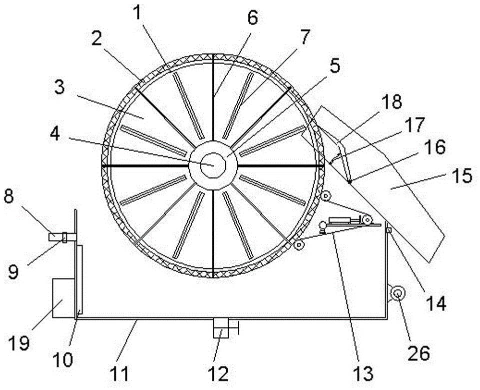
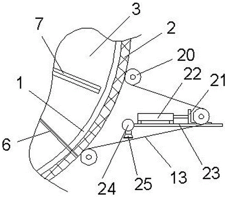
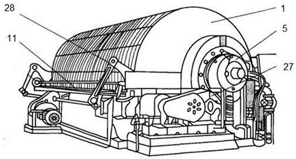
[0023] see Figure 1~3 , the present invention provides a technical solution: an automatic control drum vacuum filter device, including a filter drum on a frame, a distribution head 5, a transmission device 27, a stirring device 28 and a slurry storage tank 11, the filter drum The drum includes a cylindrical drum body 1, the outer wall of the drum body 1 is provided with a support filter screen 2, and the support filter screen 2 is covered with a filter cloth ...


PUM


Abstract

The invention discloses an automation-control rotary drum vacuum filter apparatus which comprises a filtering rotary drum on a rack, a distributing head, a transmission apparatus, a stirring apparatus and a material slurry storage tank. The filtering rotary drum includes a cylindrical drum body. A support filter screen is arranged on the outer wall of the drum body. A filter cloth coats the support filter screen through a plurality of guiding rollers which are all mounted on the rack. The rack is also provided with a tensional apparatus for regulating the tension of the filter cloth and a cleaning apparatus for cleaning the filter cloth. A central rotary shaft is installed in the center of the drum body, an input end of the central rotary shaft being connected to the transmission apparatus. With the central rotary shaft as an axis, a plurality of separation boards are arranged radially in the radial direction inside the drum body. A controller is arranged on an outer wall of the material slurry storage tank. The rotary drum vacuum filter apparatus has reasonable structural design, allows automatic slurry inlet and achieves automatic cleaning of the filter cloth, has good filter cloth cleaning effect and effectively ensures filter efficiency.

Description

technical field [0001] The invention relates to the technical field of drum filtering equipment, in particular to an automatic control drum vacuum filtering device. Background technique [0002] Drum vacuum filter, a type of continuous filter. The structure is similar to the drum vacuum filter and the operating principle is the same. It is a continuous filter with negative pressure as the driving force and the filter surface is on the surface of the cylindrical drum. This filter was originally used in soda making and mining industries, and later expanded to chemical, coal and sludge dehydration and other departments. [0003] Drum vacuum filter has a horizontal drum, the drum wall is perforated, and the drum surface is covered with support plate and filter cloth to form the filter surface. The space under the filter surface is divided into several separated fan-shaped filter chambers. Each filter chamber has a conduit communicating with the distribution valve. Every tim...

Claims


Application Information

Patent Timeline
IPC IPC(8): B01D33/073B01D33/46B01D33/48B01D33/72
CPCB01D33/073B01D33/466B01D33/48B01D33/72
Inventor 张英付保英宋利芬
Owner HEBI COLLEGE OF VOCATION & TECH
Why Eureka
Try Eureka