A continuous die cold stamping and drawing process for a camera bracket

A camera and die cooling technology, which is applied in the field of continuous die cold stamping and drawing of camera brackets, can solve the problems of no burrs on the surface, high camera size requirements, and high difficulty.

Active Publication Date: 2018-12-04
JIANGSU ARAINBOW PRECISION METAL TECH CO LTD
View PDF5 Cites 2 Cited by
  • Summary
  • Abstract
  • Description
  • Claims
  • Application Information

AI Technical Summary

Problems solved by technology

Because the processing difficulties of this small metal part are as follows: 1. The camera has high requirements on the size of the bracket, and there should be no rough edges on the surface; 2. The stretching of the structure is square stretching, which is extremely difficult; 3. It is required that the blanking of the product cannot be deformed

Method used


Image

  • A continuous die cold stamping and drawing process for a camera bracket
  • A continuous die cold stamping and drawing process for a camera bracket
  • A continuous die cold stamping and drawing process for a camera bracket

Examples


Embodiment

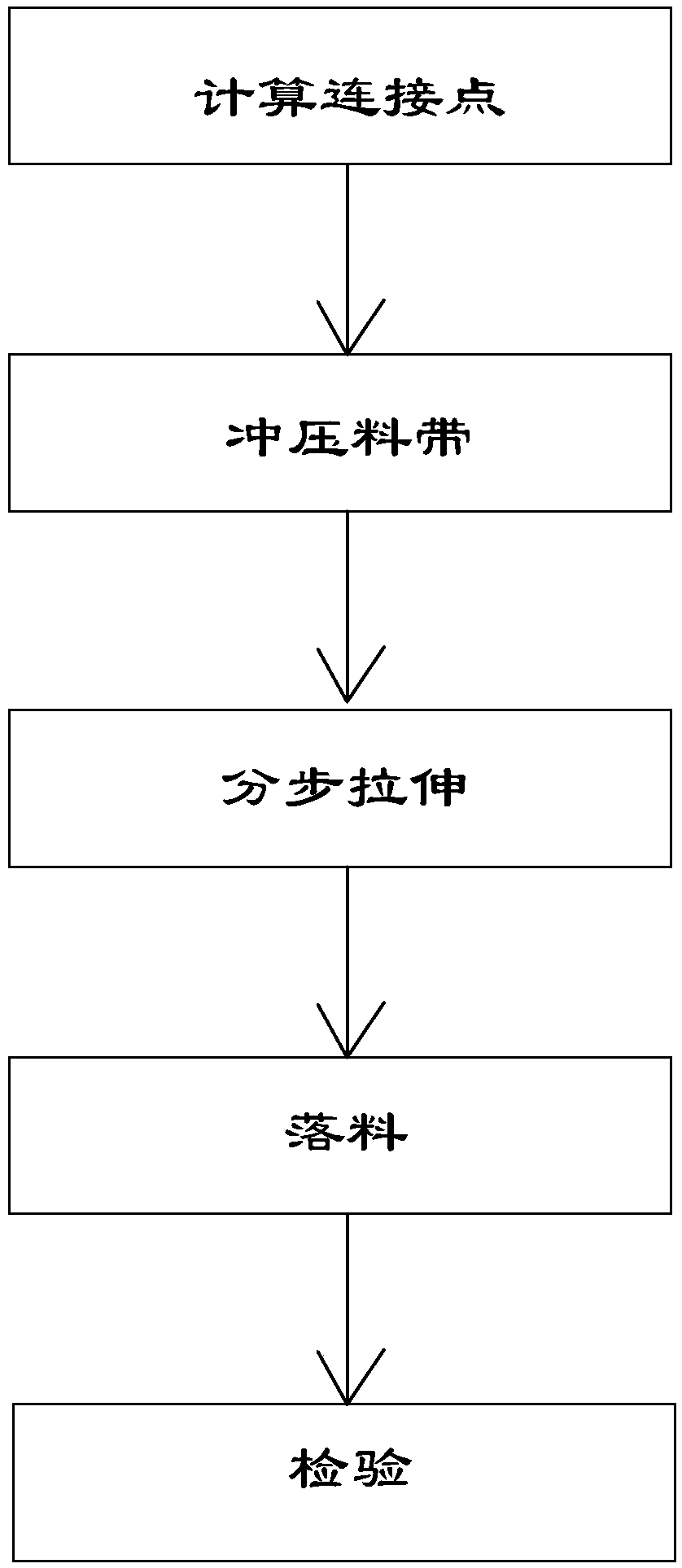
[0025] Such as figure 1 , figure 2 , image 3 and Figure 4 Shown, a kind of camera bracket continuous die cold stamping stretching process comprises the following steps:

[0026] A1, calculate the connection point of product and material belt: according to the surface area size and shape of product, utilize the plastic deformation tensile strength of material to calculate the connection point position of product and material belt;

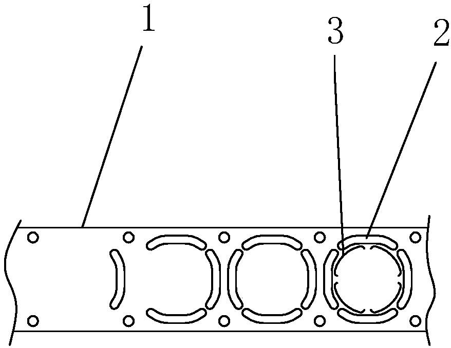
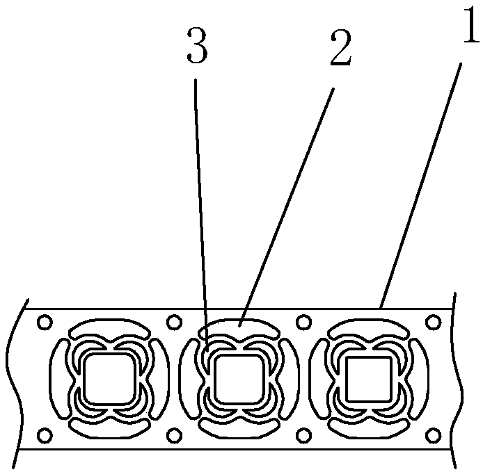
[0027] A2. Stamping material strip: punch out 4 outer ring connection points 2 on the material belt 1 that has calculated the connection points of the product and the material belt, and punch out 4 outer ring connection points 2 on the inner side between each adjacent two outer ring connection points 2. an inner ring connection point 3;

[0028] A3. Step-by-step stretching: Provide reverse tension to the inner and outer parts of the 4 outer ring connection points 2 to carry out step-by-step stretching from large to small, making full use of t...


PUM


Abstract

The invention relates to a progressive die cold punching and drawing process of a camera support. The process comprises the steps that according to the superficial area, size and shape of a product, the positions of connecting points of the product and a material belt are firstly calculated through the plastic deformation tensile strength of a material; four outer ring connecting points are punched on the material belt with the calculated connecting points of the product and the material belt, and four inner ring connecting points are punched on the inner side of the position between every two adjacent outer ring connecting points; reversed tension is provided for the inner parts and the outer parts of the four outer ring connecting points to carry out step-by-step drawing from large to small, plastic deformation of the material is fully utilized, and the depth and boundary dimension needed by the product are obtained through drawing; the drawn product and material belt are vertically arranged in the width direction, the drawn product and material belt waste are separated from the side face, and blanking is achieved; and the finished camera support obtained after blanking is comprehensively inspected. The aims that the product is prevented from being directly punched, the surface of the product has no burrs, and no deformation happens during blanking are achieved.

Description

technical field [0001] The invention relates to the field of machining of mobile phone parts, in particular to a continuous die cold stamping and stretching process for a camera bracket. Background technique [0002] The camera bracket product is a small square metal piece with 5 sides closed and one side transparent. Usually, the processing technology that people can think of is casting. But practice has proved that it is difficult to meet its product requirements. For such a small product of this kind of structure, how to produce it in a cheap and mass-produced manner? It is continuous stamping, and most stamping companies don't know how to start when they see this kind of product. Because the processing difficulties of this small metal part are as follows: 1. The camera has high requirements on the size of the bracket, and there should be no rough edges on the surface; 2. The stretching of the structure is square stretching, which is extremely difficult; 3. It is requir...

Claims


Application Information

Patent Timeline
Patent Type & Authority Patents(China)
IPC IPC(8): B21D35/00B21D22/04B21D22/20
CPCB21D22/04B21D22/20B21D35/002
Inventor 田素光
Owner JIANGSU ARAINBOW PRECISION METAL TECH CO LTD
Why Eureka
Try Eureka