
Wing aerodynamic speed reducing mechanism

An aerodynamic and decelerating mechanism technology, applied in the field of aircraft, can solve the problems of high production cost and complex opening structure of baffles

Inactive Publication Date: 2016-12-21
天津津宇凯创航空科技发展有限公司
View PDF9 Cites 4 Cited by
  • Summary
  • Abstract
  • Description
  • Claims
  • Application Information

AI Technical Summary

Problems solved by technology

[0002] At present, various countries are developing new take-off and landing methods, and deceleration is one of the important topics. When the aircraft lands, in order to accelerate the deceleration effect, baffles will be added on the wings. When landing, open the baffles to increase wind resistance. Improve the deceleration effect, but the current baffle opening structure is complicated and the production cost is high

Method used


Image

  • Wing aerodynamic speed reducing mechanism
  • Wing aerodynamic speed reducing mechanism

Examples


Embodiment Construction

[0019] The present invention will be further described below in conjunction with embodiment:

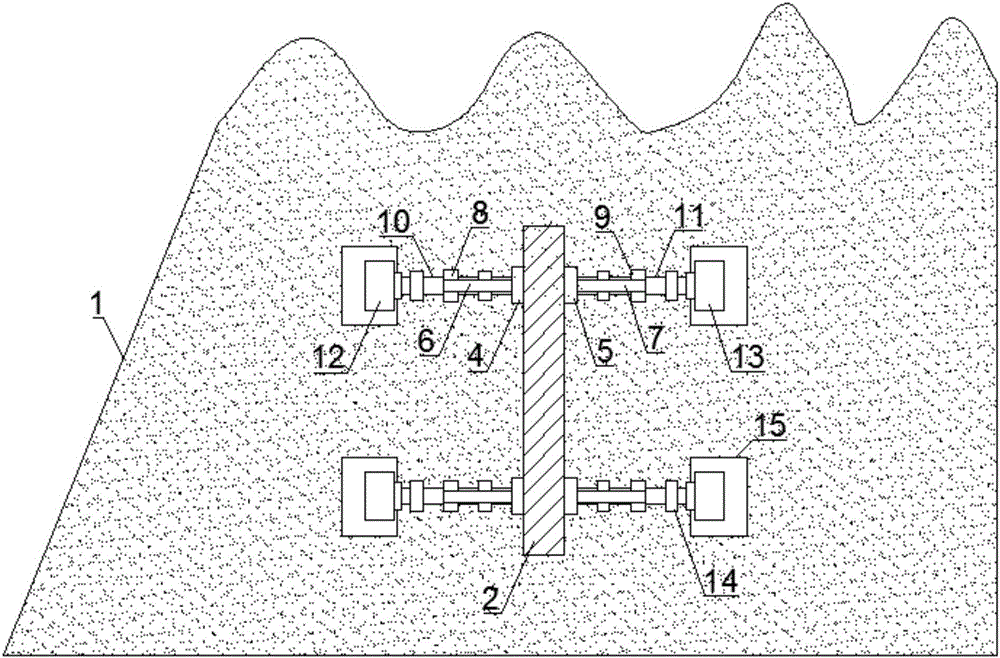
[0020] Such as Figure 1-2 As shown, the wing aerodynamic speed reduction mechanism provided by the present invention includes a wing 1, a speed brake 2 and a controller, the speed brake 2 is arranged inside the wing 1 along the vertical direction, and the upper surface of the wing 1 is connected to the An opening is provided at a position corresponding to the upper surface of the speed brake 2, and a movable plate 3 that is airtightly fitted with the opening is provided on the opening, and the lower part of the movable plate 3 is fixedly connected with the upper surface of the speed brake 2;

[0021] Corresponding positions on both sides of the lower part of the speed brake 2 are fixedly connected with a first fixed block 4 and a second fixed block 5 respectively, and a first tie rod 6 and a first tie rod 6 are hinged on the first fixed block 4 and the second fixed block 5 respectiv...


PUM


Abstract

The invention provides a wing aerodynamic speed reducing mechanism, which includes a wing, an airbrake and a controller. The airbrake is disposed inside the wing, an opening is disposed at a position corresponding to that of the airbrake upper surface on the wing upper surface, the opening is provided with a movable plate, and the lower part of the movable plate is in fixed connection with the airbrake upper surface. First fixation blocks and second fixation blocks are respectively arranged at corresponding positions on two sides at the lower part of the airbrake, and are hinged to first pull rods and second pull rods respectively, the other ends of the first pull rods and second pull rods are hinged to first sliding blocks and second sliding blocks respectively, the first sliding blocks and the second sliding blocks are in threaded connection with first screw rods and second screw rods respectively, and the first screw rods and the second screw rods are connected to the output shafts of first screw rod motors and the output shafts of second screw rod motors. The wing aerodynamic speed reducing mechanism provided by the invention has the characteristics of simple structure and stable operation, and can quickly open the airbrake to meet operating requirements.

Description

technical field [0001] The invention belongs to the technical field of aircraft, and in particular relates to a wing aerodynamic deceleration mechanism. Background technique [0002] At present, various countries are developing new take-off and landing methods, and deceleration is one of the important topics. When the aircraft lands, in order to accelerate the deceleration effect, baffles will be added on the wings. When landing, open the baffles to increase wind resistance. Improve the deceleration effect, but the current baffle opening structure is complicated, and the production cost is high. Contents of the invention [0003] The object of the present invention is to solve the above-mentioned problems in the prior art, and provide a wing aerodynamic deceleration mechanism with simple structure, stable operation, and the ability to quickly open the deceleration brake. [0004] The technical solution adopted by the present invention to solve its technical problems is: ...

Claims


Application Information

Patent Timeline
Patent Type & Authority Applications(China)
IPC IPC(8): B64C9/32
CPCB64C9/323
Inventor 陈鹏韩洁杰
Owner 天津津宇凯创航空科技发展有限公司
Learn More