
An ultra-compact and high-efficiency racemic lobe mixing exhaust system structure

An exhaust system and lobe technology, which is applied in the field of high-performance aviation gas turbofan engines, can solve the problems of increasing the difficulty of the lobe mixer, increasing the total pressure loss and thrust loss, and limited tolerance, so as to improve the mixing efficiency and output thrust, improve the thrust-to-weight ratio, and strengthen the effect of anti-inlet pre-swirl ability

Active Publication Date: 2017-10-03
中科航星科技股份有限公司
View PDF5 Cites 0 Cited by
  • Summary
  • Abstract
  • Description
  • Claims
  • Application Information

AI Technical Summary

Problems solved by technology

However, the lobe mixer also inevitably has some disadvantages mentioned above. It has a certain anti-pre-swirl ability, but the tolerance to the upstream pre-swirl is very limited, and the outlet airflow angle of the low-pressure turbine exceeding 10° will be As a result, flow separation occurs on the surface of the lobe, and a recirculation zone appears downstream of the central cone, which greatly increases the total pressure loss and thrust loss, which in turn increases the difficulty of matching the lobe mixer with the low-pressure turbine, especially with the high-load low-pressure turbine. match

Method used


Image

  • An ultra-compact and high-efficiency racemic lobe mixing exhaust system structure
  • An ultra-compact and high-efficiency racemic lobe mixing exhaust system structure

Examples


Embodiment Construction

[0028] In order to make the purpose, technical solutions and advantages of the present invention clearer, the present invention will be further described in detail below in conjunction with the examples. The following examples are explanations of the present invention and the present invention is not limited to the following examples.

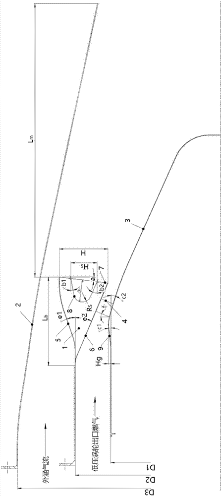
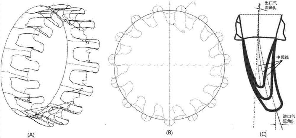
[0029] see figure 1 , 2 , the ultra-compact and high-blending efficiency derotation lobe mixing exhaust system structure of the present invention is suitable for high-performance small and medium bypass ratio aviation turbofan engines, and consists of a derotation lobe mixer 1, a mixing nozzle 2, and a belt drum The central cone 3 and the airfoil rib 4 are composed of four parts, wherein the derotation lobe mixer 1 is composed of a peak lobe 5 and a "special-shaped blade-like" wave trough lobe 6. The center cone is composed of a straight section, a bulge 9 and a tail cone. The derotation lobe mixer 1 and the center cone 3 with a bulge are conn...


PUM


Abstract

The invention relates to the technical field of mixed air exhaust systems, in particular to an ultra-compact and high-mixing-efficiency air exhaust system structure adopting a de-swirl lobe mixer. The ultra-compact and high-mixing-efficiency air exhaust system structure adopting the de-swirl lobe mixer is especially suitable for a high-performance aviation gas turbine fan engine. The ultra-compact and high-mixing-efficiency air exhaust system structure adopting the de-swirl lobe mixer comprises the de-swirl lobe mixer with an inlet flow angle, a central cone with a bump and a mixing spray tube; a plurality of wing type reinforcing rib connecting structures are arranged between the de-swirl lobe mixer and the central cone; the lower ends of wing type reinforcing ribs are fixedly connected to the central cone with the bump; the upper ends of the wing type reinforcing ribs are fixedly connected to a de-swirl lobe trough; a trough lobe is a specially-shaped blade structure; the specially-shaped blade has an inlet flow angle; the side wall of the lobe mixer is subjected to concave sector cutting processing; and distances between the front edges of the lower ends of the reinforcing ribs to bump slope of the central cone are 0-3 times chord length of the reinforcing ribs. The ultra-compact and high-mixing-efficiency air exhaust system structure adopting the de-swirl lobe mixer has a plurality of advantages of being high in mixing efficiency, strong in pre-whirling resistance, compact in structure, high in reliability, low in processing and maintaining cost, and the like.

Description

technical field [0001] The invention relates to the technical field of mixed exhaust systems, in particular to an ultra-compact and high-mixing-efficiency racemic lobe mixed exhaust system structure, which is especially suitable for high-performance aviation gas turbofan engines. Background technique [0002] An important characteristic difference of various types of small and medium bypass ratio aviation gas turbofan engines is the difference in the type of exhaust system components, which is different from the large bypass ratio aeroengine, which adopts the separate exhaust structure of internal and external bypass jets without pre-mixing Compared with the aero-engine exhaust system, the small and medium ducts use the mixed exhaust system in which the internal and external jets are pre-mixed in the tail nozzle. [0003] Annular mixed exhaust system is the first mixed exhaust type used, such as F100-PW-129 adopts simple annular mixed exhaust type, the advantages of this mix...

Claims


Application Information

Patent Timeline
Patent Type & Authority Patents(China)
IPC IPC(8): F02K1/34F02K1/46
CPCF02K1/34F02K1/46
Inventor 雷志军龚建波张燕峰卢新根朱俊强徐纲苏尚美
Owner 中科航星科技股份有限公司
Learn More