
A Parametric Design Method of Lobe Mixer

A parametric design, mixer technology, applied in design optimization/simulation, special data processing applications, geometric CAD, etc., can solve the problems of increasing total pressure loss and thrust loss, limited adaptation space, and difficult design, and achieves a reduction in Jet mixing noise, improve jet mixing efficiency, and achieve reasonable matching effect

Active Publication Date: 2020-07-10
INST OF ENGINEERING THERMOPHYSICS - CHINESE ACAD OF SCI
View PDF3 Cites 0 Cited by
  • Summary
  • Abstract
  • Description
  • Claims
  • Application Information

AI Technical Summary

Problems solved by technology

However, the geometric structure of the lobe mixer is complex, which makes its design more difficult, and the influence of its parameters is not yet fully clear
In addition, due to the increase in the load of the low-pressure turbine stage, the outlet flow of the low-pressure turbine has a circumferential airflow angle. The conventional lobe mixer itself has a certain anti-pre-swirl ability, but the space for adapting to the upstream pre-swirl is very limited, more than 10 A low-pressure turbine outlet airflow angle of ° will cause flow separation on the lobe surface, and a recirculation zone will appear downstream of the central cone, which greatly increases the total pressure loss and thrust loss, which in turn increases the difficulty of matching the lobe mixer with the low-pressure turbine , especially matching with the high load low pressure turbine
[0005] In order to solve the problems existing in conventional lobe mixers, scholars have conceived a new type of anti-prerotation lobe mixer, which can solve the negative effects of upstream prerotation to a certain extent.
However, due to the more complex structure of the anti-pre-swirl lobe mixer, its design and optimization are extremely difficult, making it difficult to carry out research work on it, so that the matching law between the new anti-pre-swirl lobe mixer and the outlet airflow of the upstream low-pressure turbine is still unclear. Not clear, and the mode of action with the downstream mixing nozzle is not yet clear

Method used


Image

  • A Parametric Design Method of Lobe Mixer
  • A Parametric Design Method of Lobe Mixer
  • A Parametric Design Method of Lobe Mixer

Examples


Embodiment Construction

[0044] In order to make the purpose, technical solutions and advantages of the patent of the present invention clearer, the patent of the present invention will be further described in detail below in conjunction with the examples. The following examples are explanations of the patent of the present invention and the patent of the present invention is not limited to the following examples.

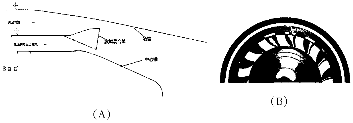
[0045] see figure 1 , The structure of the lobe mixer exhaust system that the present invention relates to mainly includes a lobe mixer, a central cone, and a mixing nozzle. The lobe mixer is used to accelerate the inner and outer airflow of the high-performance aviation gas turbofan engine, and the inner lobe of the lobe mixer mainly interacts with the outlet gas of the low-pressure turbine of the engine.

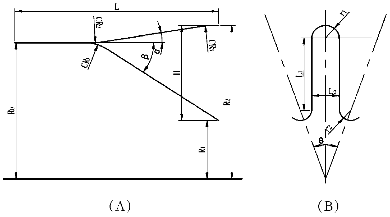
[0046] see figure 2 , the parametric modeling parameters of the conventional lobe mixer used in the present invention and the definition of each parameter, the defined parameters are...


PUM


Abstract

The invention relates to the technical field of mixed air exhaust systems of aviation gas turbofan engines, and particularly to a parameterization design method of a lobe mixer. The method is especially suitable for use in parameterization design and parameter optimization of the novel lobe mixer. The invention aims to solve the problem that design difficulty of the pre-whirling-resistance lobe mixer is high, and achieve the purpose of parameterization design through using parameters to define geometry of the lobe mixer in a design process. The method includes the steps of parameterization design of a basic lobe mixer, parameterization showing of the basic lobe mixer, two-dimensional design of the target lobe mixer, three-dimensional design of the target lobe mixer, novel parameterization trailing edge modification of the target lobe mixer and the like. Curves to which the invention relates can be all of straight lines, parabolas, polynomial curves, Bezier curves, spline curves and Nurbs curves. The method has many advantages of simple and effective design, less control parameters, smooth curved surfaces and the like.

Description

technical field [0001] The present invention relates to the technical field of mixed exhaust system of aviation gas turbofan engine, especially relates to the matching technology of low-pressure turbine outlet of aero-engine and mixed exhaust system, the aerodynamic layout of ultra-compact, high-mixing efficiency and high-performance aero-engine exhaust system, especially the lobe mixing Parametric design of the device. Background technique [0002] The exhaust system of aviation gas turbine fan engine is divided into two forms: separate exhaust and mixed exhaust. For civil turbofan engines with large bypass ratio, the exhaust system usually adopts the form of separate exhaust, while for gas turbofan engines with small and medium bypass ratios, the exhaust system mostly adopts the hybrid exhaust system. [0003] Early mixed exhaust systems mostly used annular exhaust mixing pipes. For example, F100-PW-129 adopted a simple annular mixed exhaust type. This mixed exhaust layou...

Claims


Application Information

Patent Timeline
Patent Type & Authority Patents(China)
IPC IPC(8): G06F30/20G06F30/17
CPCG06F30/17G06F30/20
Inventor 柴猛雷志军张燕峰卢新根朱俊强徐纲
Owner INST OF ENGINEERING THERMOPHYSICS - CHINESE ACAD OF SCI
Learn More