Design method of a two-way roller type vibration isolation device

A design method and roller-type technology, applied in the direction of shock absorbers, mechanical equipment, springs/shock absorbers, etc., can solve the problems of large occupied space and complex structure of the roller isolation device, so as to reduce the occupied space and have a simple structure. , the effect of obvious social benefits

Active Publication Date: 2018-02-27
CHINA AVIATION PLANNING & DESIGN INST GRP
View PDF5 Cites 0 Cited by
  • Summary
  • Abstract
  • Description
  • Claims
  • Application Information

AI Technical Summary

Problems solved by technology

[0004] The invention relates to a design method of a two-way roller-type shock-isolating device, which aims to solve the technical problems that the traditional roller-type shock-isolating device has a complex structure, requires up and down orthogonal double-layer tracks, and occupies a large space

Method used


Image

  • Design method of a two-way roller type vibration isolation device
  • Design method of a two-way roller type vibration isolation device
  • Design method of a two-way roller type vibration isolation device

Examples


Embodiment 1

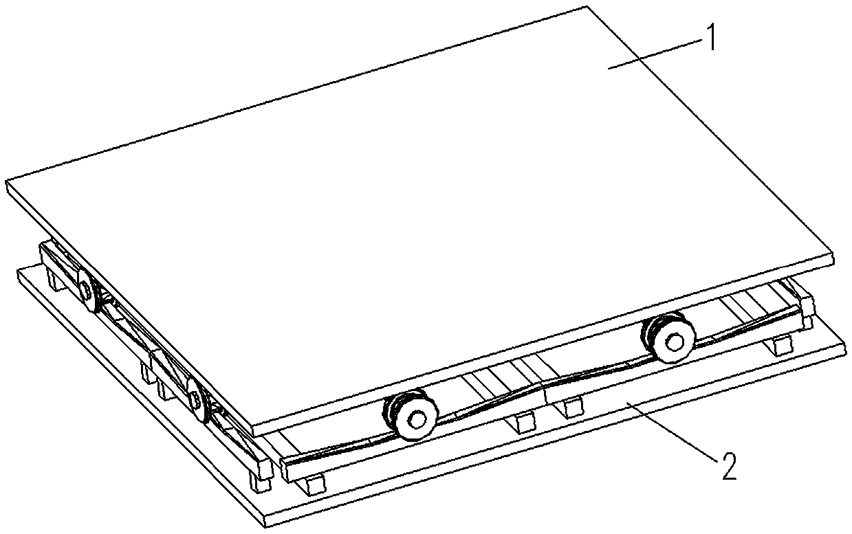
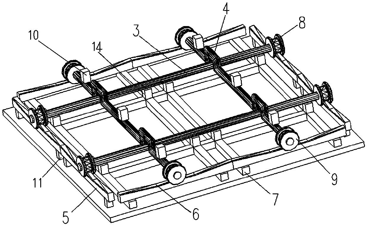
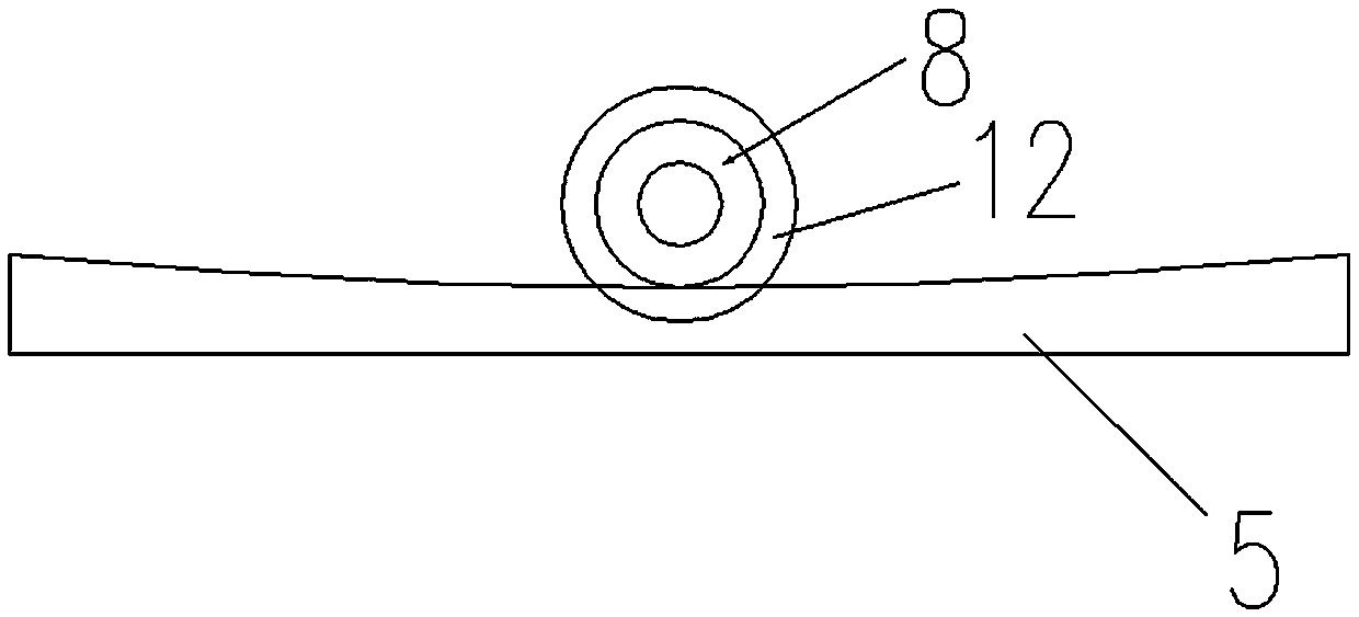
[0066] In this embodiment, the upper surface of the fixed curvature track 5 is provided with two sections of smooth arc along its long axis; the upper surface of the floating curvature track 6 is provided with two sections of smooth arc along its long axis; Adjusting the radius of curvature of the fixed curvature track 5 and the floating curvature track 6 can realize shock isolation effects in two directions. Connected on the fixed curvature track 5; the floating track rollers 9 correspond to the smooth arc surface on the floating track 6, there are two pairs, and are slidably connected on the floating track 6.

[0067] In the present embodiment, a long fixed track wheel shaft 3 is connected between each pair of fixed track rollers 8; a long floating track wheel shaft 4 is connected between each pair of floating track rollers 9; the fixed track wheel shaft 3 and The floating rail axle 4 is located in the same horizontal plane and is arranged in a cross; in order to reduce the ...

Embodiment 2

[0096] like Figure 11-18 In this embodiment, the upper surface of the fixed curvature track 5 is provided with two sections of smooth arc along its long axis; the upper surface of the floating curvature track 6 is provided with two sections of smooth arc along its long axis; Adjusting the radius of curvature of the fixed curvature track 5 and the floating curvature track 6 can realize shock isolation effects in two directions. Connected on the fixed curvature track 5; the floating track rollers 9 correspond to the smooth arc surface on the floating track 6, there are two pairs, and are slidably connected on the floating track 6.

[0097] In this embodiment, each fixed track roller 8 is connected to a fixed track wheel shaft 3 in the axial direction; each floating track roller 9 is connected to a floating track wheel shaft 4 in the axial direction.

[0098] There is no contact between each fixed track axle 3 and the floating track axle 4.

[0099] In this embodiment, in orde...


PUM


Abstract

The invention provides a bidirectional roller type shock insulation device and a design method. The bidirectional roller type shock insulation device sequentially comprises a bottom plate, a rail support set, a curvature rail set, a roller set and a top plate from bottom to top. The curvature rail set comprises fixed curvature rails and floating curvature rails. A rectangular structure is formed by the fixed curvature rails and the floating curvature rails along the four edges of the bottom plate sequentially and alternately in an enclosed mode. The roller set comprises fixed rail rollers and floating rail rollers. The bidirectional roller type shock insulation device is simple in structure, the purpose of shock insulation is achieved through rolling of the rollers on the curvature rails, and different shock insulation effects are achieved by adjusting the curvature radius of the rails; the rails are arranged in the same layer, so that the height of the shock insulation device is decreased; and the occupied space of the device is reduced.

Description

technical field [0001] The invention relates to the technical field of shock absorption and isolation, in particular to a design method for a two-way roller type shock isolation device used in the technical field of shockproof protection of cultural relics. Background technique [0002] Museums are the carriers that make cultural relics come alive in the protection and utilization of cultural relics. A large number of movable cultural relics flow to museums for centralized storage, which also increases the possibility of massive damage under sudden disasters such as earthquakes. More than 60% of museums in my country are located in a strong earthquake-prone earthquake zone. The 5.12 Wenchuan earthquake in 2008 caused damage to no less than 2,766 cultural relics in the collection. Anti-seismic measures for cultural relics in museums can be divided into two types: anti-seismic and anti-seismic methods. As far as the current situation of floating cultural relics in our country’...

Claims


Application Information

Patent Timeline
Patent Type & Authority Patents(China)
IPC IPC(8): F16F7/00F16F7/06
CPCF16F7/00F16F7/06F16F2222/04F16F2232/02
Inventor 葛家琪管志忠马伯涛张曼生宋毛毛黄季阳张玲张国军刘鑫刚
Owner CHINA AVIATION PLANNING & DESIGN INST GRP
Why Eureka
Try Eureka