
High-precision bridge deformation detection method based on radio frequency phase measurement technology

A technology of phase measurement and detection method, applied in electromagnetic measurement devices, electric/magnetic solid deformation measurement, etc., can solve the problem of not fully satisfying the high frequency of bridge vibration continuity, and achieve the effect of health monitoring

Active Publication Date: 2018-12-07
GUANGZHOU UNIVERSITY
View PDF5 Cites 0 Cited by
  • Summary
  • Abstract
  • Description
  • Claims
  • Application Information

AI Technical Summary

Problems solved by technology

Although these measurement methods have their own characteristics and application environments, they also have their limitations and cannot fully meet the requirements of continuous (multi-point), high-frequency (high-frequency), and real-time (dynamic) measurement of bridge vibration.

Method used


Image

  • High-precision bridge deformation detection method based on radio frequency phase measurement technology
  • High-precision bridge deformation detection method based on radio frequency phase measurement technology
  • High-precision bridge deformation detection method based on radio frequency phase measurement technology

Examples


Embodiment 1

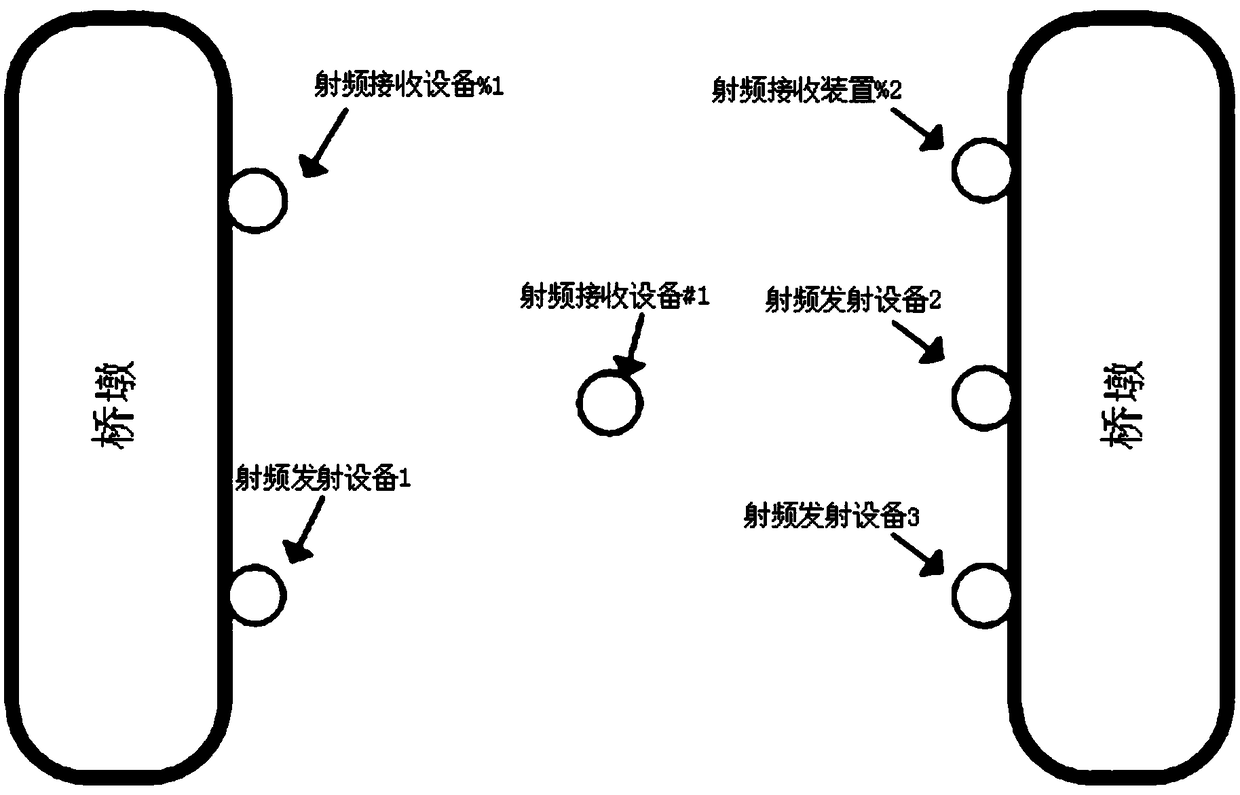
[0092] Such as figure 1 As shown, consider a certain span of a bridge with a span of 300m. One radio frequency transmitting device (side A, number: 1) is fixedly installed on one side of the bridge span, and two sets are fixedly installed on the other side (side B, number: 2, 3), the two public RF frequencies are 315MHz and 433MHz, and the two frequencies can be combined into f 1 =748MHz is fine frequency, f 2 = 118MHz is the coarse frequency; one set of radio frequency receiving equipment is fixedly installed on each side of the pier on both sides (number of side A: %1, number of side B: %2), the distance between the radio frequency receiving equipment and the radio frequency transmitting equipment is greater than 0.4m, and the radio frequency receiving equipment of side B The equipment has 2 signal channels, and the radio frequency receiving equipment on side A has 1 signal channel; a radio frequency receiving device (number: #1) is installed in the mid-span, and this recei...


PUM


Abstract

The invention relates to a bride deformation detection method, and the method comprises the steps: installing one piece of radio frequency transmitting equipment and one piece of radio frequency receiving equipment on each pier of a bridge at one side, installing two pieces of radio frequency transmitting equipment and one piece of radio frequency receiving equipment, and installing a plurality of pieces of radio frequency receiving equipment at a midspan measurement point; enabling the radio frequency receiving equipment on the piers at each side to receive radio frequency signals from the radio frequency transmitting equipment on the piers at the same side and span, and enabling the radio frequency receiving equipment at the midspan measurement point to receive the radio frequency signals from the radio frequency transmitting equipment on the piers at the two sides and the same span; enabling the radio frequency receiving equipment to carry out the phase measurement of the radio frequency signals, determining the distances from the radio frequency receiving equipment on the piers at the same side and each span to the radio frequency receiving equipment, and calculating the frequency offset according to the distances; correcting the actual measurement distances from the radio frequency transmitting equipment to the radio frequency receiving equipment at the midspan measurement point according to the frequency offset; calculating the position coordinate values of the radio frequency receiving equipment at the midspan measurement point according to the corrected actual measurement distances; and calculating the deformation of the bridge according to the position coordinate values.

Description

technical field [0001] The invention relates to the fields of bridge monitoring and radio frequency distance measurement, in particular to a high-precision bridge deformation detection method based on radio frequency phase measurement technology. Background technique [0002] Real-time deformation monitoring of large bridges is very necessary during bridge construction and operation. Through real-time deformation monitoring of large bridge structures, the deformation and deformation laws of the bridge can be grasped, so as to ensure the safe and healthy operation of the bridge structure and avoid the occurrence of catastrophic accidents; The verification of design rationality and the evaluation of bridge operating life and bearing capacity are of great practical significance. At present, the traditional monitoring methods of bridge deformation mainly include sensors, accelerometers, conventional geodetic technology, laser interferometer, conventional geodetic (total station...

Claims


Application Information

Patent Timeline
Patent Type & Authority Patents(China)
IPC IPC(8): G01B7/16
CPCG01B7/16
Inventor 杨红刘夏平
Owner GUANGZHOU UNIVERSITY
Learn More