
Groove depth measurement apparatus and method for measuring groove depth

A technology for measuring devices and measuring tanks, which is applied in the direction of measuring devices and instruments, and can solve problems such as difficult online measurement and low efficiency

Inactive Publication Date: 2016-12-21
AVIC HARBIN BEARING
View PDF7 Cites 0 Cited by
  • Summary
  • Abstract
  • Description
  • Claims
  • Application Information

AI Technical Summary

Problems solved by technology

[0003] The purpose of the present invention is to solve the problem that it is difficult to realize on-line measurement and low efficiency of the depth of the end surface oil groove on the machine tool at present, and to provide a groove depth measuring device and a method for measuring the groove depth with it

Method used


Image

  • Groove depth measurement apparatus and method for measuring groove depth
  • Groove depth measurement apparatus and method for measuring groove depth
  • Groove depth measurement apparatus and method for measuring groove depth

Examples


specific Embodiment approach 1

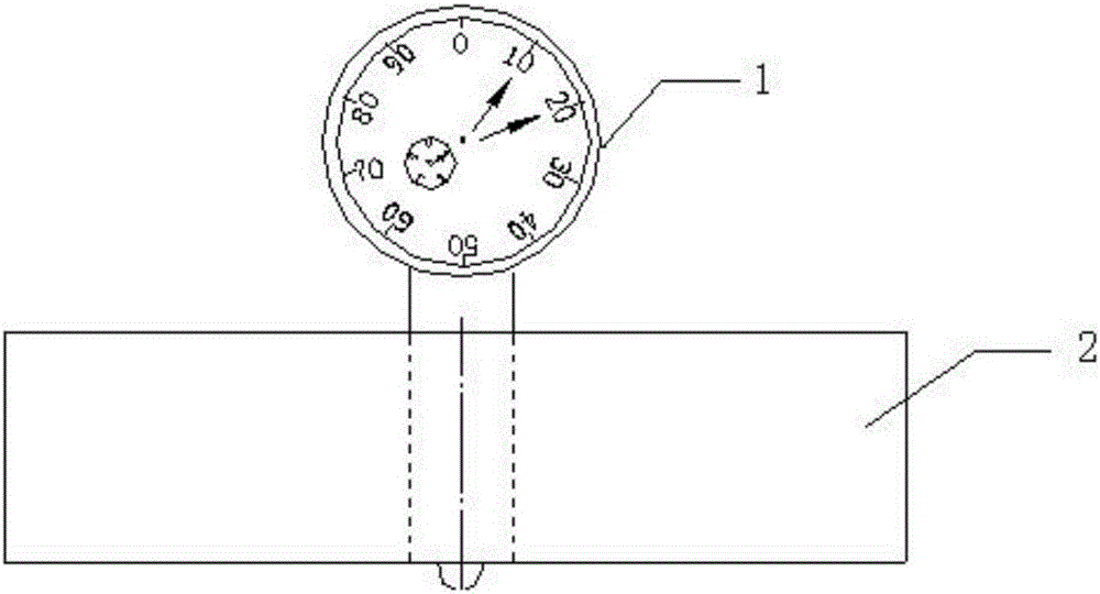
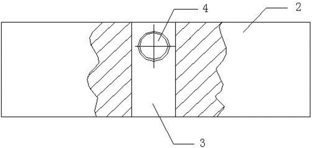
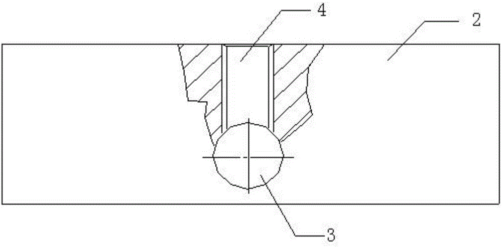
[0024] DETAILED DESCRIPTION OF THE PREFERRED EMBODIMENT 1. A groove depth measuring device in this embodiment includes a measuring instrument 1 and an instrument groove block 2;

[0025] The instrument tank block 2 is a cube structure;

[0026] The top surface of the instrument tank block 2 is provided with a through hole 3 penetrating the bottom surface, and a measuring instrument 1 is inserted in the through hole 3;

[0027] A threaded hole 4 communicating with the through hole 3 is provided on the side of the instrument tank 2 , and a screw rod for fixing the measuring instrument 1 is screwed into the threaded hole 4 .

[0028] This implementation mode designs a special groove depth measuring device for the current problem that the depth of the oil groove on the end face is difficult to achieve online measurement on the machine tool and the efficiency is low. After the oil groove on the end face is processed, it can be measured online on the machine tool. When the unqualifi...

specific Embodiment approach 2

[0030] Embodiment 2: The difference between this embodiment and Embodiment 1 is that the meter tank block 2 is a cuboid. Other steps and parameters are the same as those in the first embodiment.

specific Embodiment approach 3

[0031] Embodiment 3: This embodiment differs from Embodiment 1 or Embodiment 2 in that the perpendicularity between the through hole 3 and the bottom surface is not greater than 0.1 mm. Other steps and parameters are the same as those in Embodiment 1 or 2.


PUM

PropertyMeasurementUnit
Verticalityaaaaaaaaaa
Diameteraaaaaaaaaa

Abstract

The invention discloses a groove depth measurement apparatus and a method for measuring a groove depth, belongs to the field of detection of a bearing with an oil groove structure, and specifically relates to a groove depth measurement apparatus and a method for measuring a groove depth by use of same, for the purpose of solving the problems of difficult online measurement of an end-surface oil groove depth on a machine tool and low efficiency in the prior art. Such a product comprises a measurement instrument and an instrument groove, wherein the instrument groove is provided with a through hole and a threaded hole which communicate with each other. The method comprises the following steps: 1, the measurement instrument is inserted into the through hole, the position of an oil-free groove at the end surface of a detected workpiece is taken as an alignment reference surface, tthe apparatus is firstly placed on the end surface of the oil-free groove, the measurement instrument is pressed down, and then the measurement instrument is fixed through a screw rod in the threaded hole; and 2, the end surface of the detected workpiece and an oil groove are wiped clean, it is ensured that the bottom surface of the instrument groove is in close contact with the end surface at the oil groove side of the detected workpiece, the instrument groove is moved to enable the gauge head of the measurement instrument to be disposed at a middle position in the oil groove, and thus the groove depth is measured.

Description

technical field [0001] The invention belongs to the field of bearing detection with an oil groove structure, and in particular relates to a groove depth measuring device and a method for measuring the groove depth by using the same. Background technique [0002] There are bearings with an oil groove structure on the end face of the inner ring or outer ring of the bearing. The depth of the oil groove on the end face is usually measured with a G904 or G905 bearing-specific instrument, but this measurement method has the following disadvantages: 1. Use a G904 or G905 bearing-specific instrument to measure the end face The depth of the oil tank must be measured by removing the workpiece from the machine tool and placing it on the instrument platform. It is impossible to judge whether the processing quality is qualified on the machine tool. When the measurement fails, repeated clamping and processing are required, and online measurement cannot be realized; 2. The control instrume...

Claims


Application Information

Patent Timeline
IPC IPC(8): G01B21/18
CPCG01B21/18
Inventor 孙怀全罗志刚马驰杨志军佐景涛王慧敏赵生明张长之王淼金宏宇张翔赵立新苏海宇宁仁强
Owner AVIC HARBIN BEARING
Learn More