
Plate spring S-deformation stand test mechanism

A bench test and leaf spring technology, applied in the field of leaf spring S deformation bench test mechanism, can solve the problems of poor safety, stability and reliability of the leaf spring bench test mechanism, achieve long life and reduce equipment maintenance , cost-saving effect

Active Publication Date: 2016-12-21
ANHUI JIANGHUAI AUTOMOBILE GRP CORP LTD
View PDF5 Cites 1 Cited by
  • Summary
  • Abstract
  • Description
  • Claims
  • Application Information

AI Technical Summary

Problems solved by technology

[0011] The purpose of this invention is to provide a kind of plate spring S deformation bench test mechanism, to solve the problem of poor safety, stability and reliability of the leaf spring bench test mechanism of the prior art, and can carry out leaf spring S deformation test, Accurately analyze the stress and deformation during S-shaped deformation to ensure the reliability of the vehicle when braking or starting

Method used


Image

  • Plate spring S-deformation stand test mechanism
  • Plate spring S-deformation stand test mechanism
  • Plate spring S-deformation stand test mechanism

Examples


Embodiment Construction

[0048] The technical solution of the present invention is described in detail below through the examples, and the following examples are only exemplary and can only be used to explain and illustrate the technical solution of the present invention, rather than being interpreted as a limitation to the technical solution of the present invention.

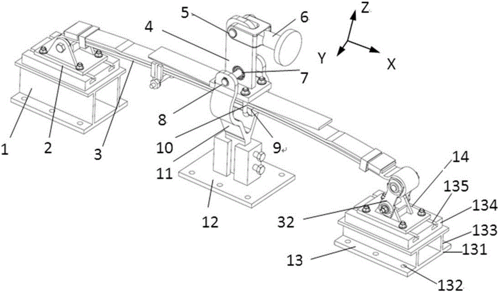
[0049] The invention provides a leaf spring S-deformation bench test mechanism, such as Figure 2 to Figure 7 As shown, it includes front support 1, roll ear bracket 2, leaf spring assembly for test 3, backing plate with force arm 4, pin shaft 5, fork-shaped test force input shaft 6, bearing 7, rotating shaft 8, and lower pad Plate 9, U-bolt 10, rotating shaft support 11, middle support 12, rear support 13, hanger support 14.

[0050] The height of the front support 1 is greater than the height of the rear support 13 .

[0051] The roll ear bracket 2 is fixed on the front support 1; the front end of the leaf spring assembly 3 to be te...


PUM


Abstract

The invention relates to a plate spring S-deformation stand test mechanism. The plate spring S-deformation stand test mechanism comprises a front bearer, a spring eye support, a tested plate spring assembly, a moment-arm-equipped backing plate, a pin, a fork-shaped test force input shaft, a bearing, a rotating shaft, a lower backing plate, U-shaped bolts, a rotating shaft support, a middle bearer, a rear bearer and a hanger support, wherein the height of the front bearer is greater than the height of the rear bearer. According to the invention, the plate spring S-deformation stand test mechanism can guarantee the safety in a stand test process; feature and fatigue tests with different elasticity and different rigidity can be implemented; the test precision is high; the high-low match between the front bearer and the rear bearer enables the attitude and stress of the tested plate spring assembly to be consistent with whole-vehicle installation; the influences exerted by horizontal linear movement of a hydraulic cylinder on a stand test are eliminated, and distortion of the stand test is not caused; and the influences exerted on equipment by torque generated when the tested plate spring assembly generates longitudinal torsion or transverse torsion are eliminated, the life of the stand equipment is long, the equipment maintenance is reduced, and the cost is saved.

Description

technical field [0001] The invention belongs to the technical field of leaf spring detection and test equipment, in particular to a leaf spring S deformation bench test mechanism. Background technique [0002] Leaf springs (referred to as leaf springs) can be placed vertically or horizontally on the car. The latter must be provided with an additional guiding force transmission device because the longitudinal force is to be transmitted, which makes the structure complex and the quality increased, so it is only used in a small number of light and miniature vehicles. Longitudinal leaf springs can transmit various forces and moments, have a guiding function, and have a simple structure, so they are widely used in automobiles. [0003] Longitudinal leaf springs are divided into symmetrical and asymmetrical. If the distance between the fixed center of the middle part of the leaf spring on the axle (bridge) (here the bolt is called the center bolt) and the center of the coil ears...

Claims


Application Information

Patent Timeline
IPC IPC(8): G01M13/00
CPCG01M13/00
Inventor 刘守银
Owner ANHUI JIANGHUAI AUTOMOBILE GRP CORP LTD
Learn More