A support structure for a flip cover of a display

A support structure and display technology, which is applied to the structural components, instruments, and calculations of portable computers, can solve problems such as screen shaking, inconvenient opening and closing adjustments, and affecting user experience, and achieve the effect of convenient opening and closing adjustments

Active Publication Date: 2021-12-21
EASTERN COMM
View PDF14 Cites 0 Cited by
  • Summary
  • Abstract
  • Description
  • Claims
  • Application Information

AI Technical Summary

Problems solved by technology

[0002] Electronic equipment with a display, especially some portable electronic equipment, the screen of these portable self-service equipment usually adopts a clamshell design, when carrying, the display is closed, and when in use, the display is opened, similar to a laptop, but the self-service equipment The screen is a touch screen, and you need to point it with your hand during operation. In the existing design, when you touch the screen with your hand, the screen will shake, which affects the user experience, and it is inconvenient to open and close.

Method used


Image

  • A support structure for a flip cover of a display
  • A support structure for a flip cover of a display
  • A support structure for a flip cover of a display

Examples


Embodiment 1

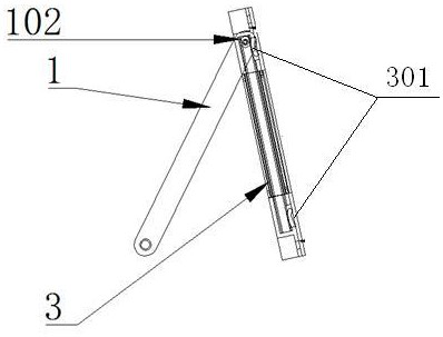
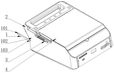
[0022] Such as figure 1 , 2 . As shown in 3, a support structure for a flip cover of a display, including a display and a body as a base 2. Both sides of the display 4 are provided with chute 3 . Corresponding to the chute, one end of the support bar 1 is connected by a hinge 101 on both sides of the base, and the other end of the support bar is provided with a slide bar 103 vertical to the support bar. In the groove, the slide bar is the axle of the roller, and the roller is the bearing, so as to facilitate the rolling of the relative chute. Such as Figure 4 As shown, when the display is not in use, the display is buckled on the base, and the support rod and the chute are in a straight line, which does not take up too much space. Such as Figure 5 As shown, when the display needs to be used, it is only necessary to open the display upward naturally, so that the display forms a triangular structure with the base and the support rod, thereby forming a stable support. Bot...

Embodiment 2

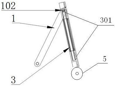
[0024] Such as Figure 6 As shown, the difference from the first embodiment is that the bottom of the display is provided with a dust removal roller 5 , that is, a roller with dust colloid on its surface. Every time the monitor is opened and closed, the dust removal roller will roll on the base, which can remove some dust on the surface of the base, so that when the monitor is buckled on the base, it will touch as little dust as possible.

Embodiment 3

[0026] Such as Figure 7 , 8 As shown, the difference from Embodiment 1 is that the display has a tumbler structure bottom 6, that is, using the principle of a tumbler toy, the bottom of the display is set to the structure of a tumbler, so that the bottom has the curvature and mass distribution of a tumbler mechanical model. At this time, the display screen of the display uses a display screen structure as thin as possible. The entire display has the performance of a tumbler, so that it will not fall down naturally. A slide groove is also provided on the base, and the hinge shaft of the support rod is arranged in the slide groove. The support rod has magnetism. For example, a magnet or Promptly be magnet to make at support bar, the two ends of support bar are two magnetic poles of magnetic field, the electromagnet 7 that magnetic field size is adjustable is all provided with at the two ends of chute. The angle of the support rod is adjusted by using the magnetic field genera...


PUM


Abstract

The invention provides a support structure for a flip cover of a display. It solves the problems of unstable display support and inconvenient opening and closing adjustment in the prior art. The cover support structure of the display includes a base and a display. A chute is provided on the side of the display. One end of the support rod is connected to the hinge of the base. The roller fits in the chute. The present invention utilizes mechanisms such as slide grooves and support rods to realize stable support for the display and is convenient to open and close.

Description

technical field [0001] The invention belongs to a flip support technology, in particular to a display flip support structure. Background technique [0002] Electronic equipment with a display, especially some portable electronic equipment, the screen of these portable self-service equipment usually adopts a clamshell design, when carrying, the display is closed, and when in use, the display is opened, similar to a laptop, but the self-service equipment The screen is a touch screen, which needs to be tapped with the hand during operation. In the existing design, when the screen is tapped, the screen will shake, which affects the user experience, and the opening and closing adjustment is inconvenient. Contents of the invention [0003] The purpose of the present invention is to solve the above-mentioned problems in the existing technology, and propose a flip support structure for a display. The device can realize stable support for the display and is convenient for opening a...

Claims


Application Information

Patent Timeline
Patent Type & Authority Patents(China)
IPC IPC(8): G06F1/16
CPCG06F1/1626G06F1/166
Inventor 吴晨刘兵曹翔
Owner EASTERN COMM
Why Eureka
Try Eureka