
Printing system architecture for encoding chip-less RFID tags in real time

An RFID tag and chipless technology, which is applied in the direction of recording carriers used in machines, printed circuits, printed circuit manufacturing, etc., can solve the problem of high cost

Active Publication Date: 2016-12-21
XEROX CORP
View PDF8 Cites 10 Cited by
  • Summary
  • Abstract
  • Description
  • Claims
  • Application Information

AI Technical Summary

Problems solved by technology

As a result, inkjet technology for printing RFID antennas is not at all comparable to the lithographic imprint / etch technique described above, but the lithographic imprint / etch process cannot be effectively used to manufacture custom labels and can be costly , because doing so requires a laser ablation step

Method used


Image

  • Printing system architecture for encoding chip-less RFID tags in real time
  • Printing system architecture for encoding chip-less RFID tags in real time
  • Printing system architecture for encoding chip-less RFID tags in real time

Examples


Embodiment Construction

[0026] The present embodiment will now be described in detail, examples of which are illustrated in the accompanying drawings. Wherever possible, the same reference numbers are used in the figures to refer to the same or similar parts. It is to be understood that the structures depicted in the figures may include additional features not depicted for brevity and that the depicted structures may be eliminated or modified.

[0027]Notwithstanding that the numerical ranges and parameters setting forth the broad scope of the embodiments are approximations, the numerical values ​​set forth in the specific examples are reported as precisely as possible. Any numerical value, however, will naturally contain certain errors necessarily resulting from the standard deviation found in its respective testing measurements. Moreover, all ranges disclosed herein are to be understood to include any and all of all subranges subsumed therein. For example, a range of "less than 10" may include an...


PUM


Abstract

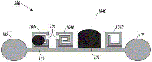
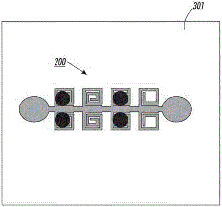
Provided is a method for encoding chipless RFID tags in real-time. The method includes exposing a chipless RFID transponder to a conductive material, the RFID transponder comprising an antenna and a plurality of resonant structures, the plurality of resonant structures together defining a first spectral signature. Each of the plurality of resonant structures includes a respective one of a frequency domain. The method also includes depositing a conductive material on at least one of the resonant structures to short the at least one of the resonant structures. The remainder of the plurality of resonant structures that are not shorted by the conductive material define a second spectral signature for the RFID transponder.

Description

technical field [0001] Embodiments described herein relate generally to customized chipless radio frequency identification (RFID) tags, methods of making and using chipless RFID tags, and systems for making customized chipless RFID tags. Background technique [0002] Radio frequency identification (RFID) technology has gained enormous popularity as a means of storing and transmitting information. RFID technology utilizes tag transponders and readers disposed on items to read and identify tags, also referred to herein as interrogators. RFID technology is broadly classified as using "active" tags or "passive" tags. Active tags have a local power source (such as a battery), so the active tags send a signal to be read by an interrogator. Active tags have a longer signal range. In contrast, "passive" labels have no internal power supply. In effect, the passive tag draws power from the reader, and the passive tag re-transmits or replies information when it receives a signal fr...

Claims


Application Information

Patent Timeline
IPC IPC(8): G06K19/07H01Q1/22H01P7/08
CPCG06K19/0723H01P7/082H01Q1/2225G06K19/0672G06K19/07773G06K2019/06253H05K1/097H05K1/0296H05K1/09H05K2203/13H05K1/092H05K3/125H05K3/1241H05K3/12
Inventor G·A·吉布森W·A·布加
Owner XEROX CORP
Learn More