Chipless RFID tag based on four-state coupled line resonator and optimization system of chipless RFID tag

A technology of RFID tags and coupling lines, applied in the field of the Internet of Things, can solve the problems of high cost, achieve the effects of reducing spectrum, realizing intelligent management, improving frequency band utilization and coding density

Active Publication Date: 2020-01-07
盐城农农炽辉科技有限公司
View PDF5 Cites 2 Cited by
  • Summary
  • Abstract
  • Description
  • Claims
  • Application Information

AI Technical Summary

Problems solved by technology

[0007] In view of this, the present invention provides a four-state cou...

Method used


Image

  • Chipless RFID tag based on four-state coupled line resonator and optimization system of chipless RFID tag
  • Chipless RFID tag based on four-state coupled line resonator and optimization system of chipless RFID tag
  • Chipless RFID tag based on four-state coupled line resonator and optimization system of chipless RFID tag

Examples


Embodiment 1

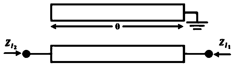
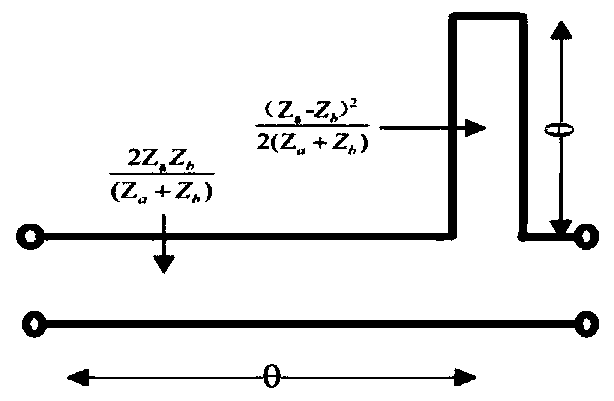
[0045] The schematic diagram and equivalent circuit of the four-state coupled line resonator proposed by the present invention are as figure 1 and figure 2 shown. The stop-band characteristics of the resonator can be determined with impedance ZI 1 and ZI 2 To represent.

[0046]

[0047]

[0048] where θ is the length of the coupled line, and Za and Zb are the characteristic impedances of the even and odd modes, respectively. When θ=π / 2, that is, when the length of the coupled line is equal to the fundamental resonance frequency f 0 At a quarter wavelength at , a fundamental stopband resonance occurs. The structure also produces stopband characteristics at all odd harmonics.

[0049] It should be noted that: f 0 Indicates the resonant frequency, the first harmonic appears at about 2f 0 place, f 1 and f 2 Also represents the center frequency. The resonant frequency often has a frequency range, the frequency range in which the resonance occurs. The frequency c...

Embodiment 2

[0064] A multi-resonator model based on a four-state coupled line resonator includes more than one four-state coupled line resonator, and each four-state coupled line resonator is connected through a microstrip transmission line.

[0065] In order to further realize the above-mentioned technical scheme, such as Figure 8 As shown, there are six four-state coupled line resonators.

[0066] In this embodiment: a six-resonator model of the proposed resonator is designed on a substrate made of FR4, with a dielectric constant of 4.4, a loss tangent of 0.02, and a thickness of 0.78 mm. The overall length and width of the structure are 29.4 and 12.6 mm, respectively. The structure is designed to maintain the frequency span of each resonator at approximately 200MHz. The frequency span between every two adjacent resonators is also chosen to be about 200MHz. For operation from 5.4 to 8 GHz, the resonator length is selected from L1 = 9.4 mm to L6 = 5.5 mm. The spacing between adjacen...

Embodiment 3

[0068] A chipless RFID tag based on the multi-resonator model, such as Figure 9 shown. The label includes a patch antenna and a multi-resonator model; two polarization modes, horizontal polarization and vertical polarization, can be realized by adjusting the patch antenna.

[0069] In this embodiment, the patch antenna is connected to the multi-resonator model through a microstrip transmission line, and presents an orthogonal polarization distribution on both sides of the multi-resonator model.

[0070] In order to further realize the above-mentioned technical scheme, such as Figure 10 As shown, the patch antenna includes a patch layer, a dielectric layer, a ground layer and a bottom plate in sequence, and the patch layer of the patch antenna is connected to the multi-resonator model through a microstrip transmission line.

[0071] In order to improve the identification speed and accuracy of the RFID system, the dual-polarized antenna has the advantages of dual-channel com...


PUM

PropertyMeasurementUnit
Thicknessaaaaaaaaaa

Abstract

The invention discloses an optimization system of a chipless RFID tag. The optimization system comprises an RFID tag, a reader-writer and a back-end server; the reader-writer is used for reading the RFID tag and transmitting data to the back-end server in a wireless or wired manner; the rear-end server is used for completing data processing and automatic intelligent management and control, whereinthe RFID tag comprises a patch antenna and the multi-resonator model, the multi-resonator model comprises more than one four-state coupling line resonator, and the four-state coupling line resonatorshave four states and are respectively coded. The chipless RFID tag provided by the invention has the good effects of optimal bandwidth, efficient and accurate identification and expandability, has the characteristics of wide identification range, direction independence and the like, and effectively improves the overall performance of a chipless RFID tag system.

Description

technical field [0001] The invention relates to the technical field of the Internet of Things, and more specifically relates to a chipless RFID tag based on a four-state coupled line resonator and an optimization system thereof. Background technique [0002] With the rapid development of information technology, the Internet of Things (IoT) has become one of the core technologies of the current new generation of technological revolution. The era of the Internet of Things is being integrated into various fields of society. It, big data, artificial intelligence, etc. are the hot areas of current social research, and their mutual integration will be the core content of the future wireless communication field. At the same time, it involves multiple industrial chains. As of the end of 2018, the number of connections of IoT devices in my country reached 1.6 billion, and it is expected to exceed 7 billion by 2020. The exponential growth of IoT devices demonstrates its huge developm...

Claims


Application Information

Patent Timeline
IPC IPC(8): G06K19/077G06K17/00
CPCG06K17/0029G06K19/0772G06K19/07773
Inventor 于银辉郑毅超李清华牟劲龙任嘉鹏杨莹潘昊
Owner 盐城农农炽辉科技有限公司
Why Eureka
Try Eureka