Band switching method, antenna and rear shell of terminal

A technology for switching frequency bands and frequency bands, applied in the field of communication, can solve the problems of poor terminal communication quality and difficult to meet antenna performance, and achieve the effects of strong versatility, good radiation performance and simple implementation.

Inactive Publication Date: 2016-12-21
SHENZHEN TINNO WIRELESS TECH
View PDF3 Cites 3 Cited by
  • Summary
  • Abstract
  • Description
  • Claims
  • Application Information

AI Technical Summary

Problems solved by technology

[0005] In view of this, the embodiment of the present invention provides a method for switching frequency bands, an antenna and a rear shell of a terminal to solve the problem that the performance of receiving and / or transmitting signals in the high-frequency band of the antenna in the prior art is difficult to meet requirements for high-frequency bands. (1710Hz~2170Hz) requires higher requirements of operators, which leads to the problem of poor communication quality of terminals

Method used


Image

  • Band switching method, antenna and rear shell of terminal
  • Band switching method, antenna and rear shell of terminal

Examples


Embodiment 1

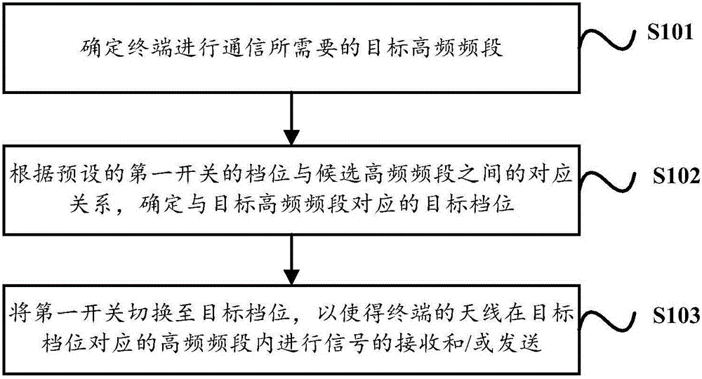
[0050] An embodiment of the present invention provides a method for switching frequency bands, in which a first switch is set in a first specified range of a feed point in an antenna of a terminal.

[0051] In the embodiment of the present invention, the first switch is set within the first specified range of the feed point of the antenna, one end of the first switch is connected to the antenna, and the other end is grounded, that is, the potential of the first switch is zero.

[0052] Specifically, in the embodiment of the present invention, the type of the first switch may include but not limited to: at least one of a switch chip, a touch switch, a multi-space switch, an inductive switch, and an intelligent switch. selection, which is not particularly limited in this embodiment of the present invention.

[0053] In a specific implementation process, determining the first designated range of the feed point may include but not limited to the following two methods:

[0054] Th...

Embodiment 2

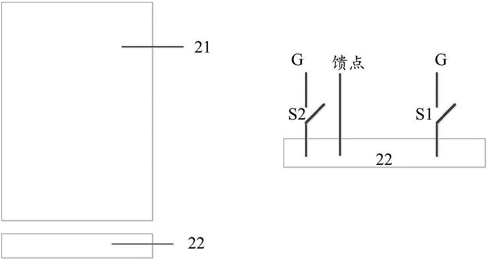
[0096] Based on the method for switching frequency bands provided in Embodiment 1 above, this embodiment of the present invention provides an antenna. Please refer to figure 2 , which is a schematic structural diagram of an antenna and a terminal rear case provided by an embodiment of the present invention. Such as figure 2 As shown, the antenna is set on the terminal, and a feed point is set in the antenna.

[0097] A first switch S1 is set on the antenna within a first specified range of the feed point, and a second switch S2 is set within a second specified range of the feed point;

[0098] One end of the first switch S1 is connected to the antenna, and the other end is grounded. The first switch is provided with at least one gear position, and each gear position corresponds to at least one candidate high-frequency frequency band;

[0099] One end of the second switch S2 is connected to the antenna, and the other end is grounded. The first switch is provided with at le...

Embodiment 3

[0104] Based on the method for switching frequency bands provided in Embodiment 1 above, this embodiment of the present invention provides a rear case of a terminal. Such as figure 2 As shown, the rear shell includes: a first shell 21 and a second shell 22 .

[0105] There is a gap between the first shell 21 and the second shell 22;

[0106] The antenna provided in the second embodiment above is disposed on the second housing 22 .

[0107] In a specific implementation process, the first casing and the second casing can be made of metal materials.

[0108] It can be understood that, in the embodiment of the present invention, the slit width between the first housing 21 and the second housing 22, and the width of the second housing 22 can be set according to actual needs. This is not particularly limited.

[0109] Since each unit in this embodiment can perform figure 1 The method shown, the part not described in detail in this embodiment, can refer to figure 1 related ins...


PUM


Abstract

Embodiments of the present invention provide a method for switching frequency bands, an antenna, and a rear case of a terminal. On the one hand, in the embodiment of the present invention, the first switch is set in the first specified range of the feed point in the antenna of the terminal, and then, by determining the target high-frequency frequency band required by the terminal for communication, according to the preset position of the first switch The corresponding relationship between the position and the candidate high-frequency frequency band, determine the target gear corresponding to the target high-frequency band, and then switch the first switch to the target gear, so that the antenna of the terminal is in the high-frequency frequency band corresponding to the target gear Receive and / or send signals within. Therefore, the technical solution provided by the embodiment of the present invention is used to solve the problem that the performance of receiving and / or transmitting signals in the high-frequency band of the antenna in the prior art is difficult to meet the requirements of operators with high requirements on the high-frequency band (1710Hz-2170Hz), This further leads to the problem that the communication quality of the terminal is poor.

Description

【Technical field】 [0001] The invention relates to the technical field of communication, in particular to a method for switching frequency bands, an antenna and a rear shell of a terminal. 【Background technique】 [0002] At present, the antenna set in the terminal will add a grounding switch near the feed point. By switching the switch to different gears, the frequency band of the antenna receiving and / or sending signals can be tuned to different low frequency bands or high frequency bands. The frequency band, that is, the high-frequency tuning and the low-frequency tuning in the prior art share a switch for adjusting the frequency band. [0003] In the course of realizing the present invention, the inventor finds that there are at least the following problems in the prior art: [0004] For antennas in the prior art, since high-frequency tuning and low-frequency tuning share a switch for adjusting the frequency band, low-frequency tuning will occupy more switch gears, result...

Claims


Application Information

Patent Timeline
Patent Type & Authority Applications(China)
IPC IPC(8): H01Q5/335H01Q5/50H01Q1/44H01Q1/22
CPCH01Q5/335H01Q1/22H01Q1/44H01Q5/50
Inventor 陈诚何鹏龙江
Owner SHENZHEN TINNO WIRELESS TECH
Why Eureka
Try Eureka