Tire inflation and sealing system

An air-tight, tire technology that is used in tire parts, tires, transportation and packaging to solve problems such as jeopardizing the ability of the donor tire to be driven

Inactive Publication Date: 2016-12-21
阿米塔伊富兰克林亚伦
View PDF5 Cites 1 Cited by
  • Summary
  • Abstract
  • Description
  • Claims
  • Application Information

AI Technical Summary

Problems solved by technology

thereby jeopardizing the ability of the donor tire to be driven (if one is indeed used)

Method used


Image

  • Tire inflation and sealing system
  • Tire inflation and sealing system
  • Tire inflation and sealing system

Examples


Embodiment Construction

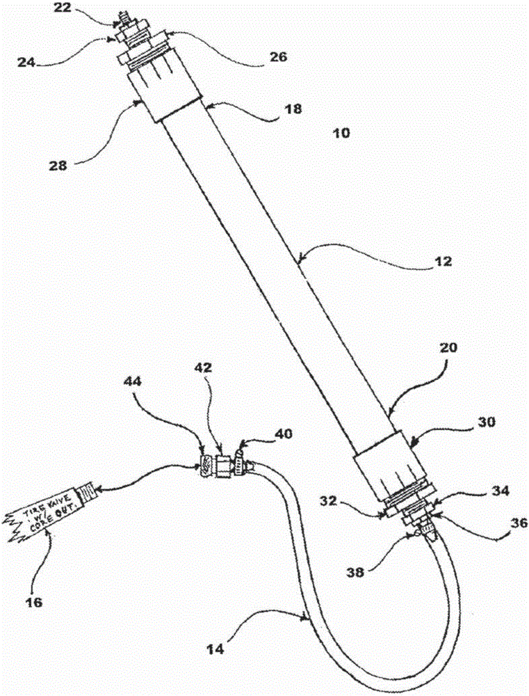
[0097] "Flow tube" hereafter refers to a flexible tube structure used as a gas cylinder and used as a channel to maintain a nearly equal cross-sectional flow surface, wherein the inner diameter of at least one end of the tube is Approximately equal to the inner diameter of a pneumatic inflation valve.

[0098] "Slime sealants" in this document refer to those liquid sealants that generally remain inactive until the sealant interacts under pressure with a puncture in a pneumatic tire. These sealants generally provide a durable and long-lasting solution for preventing punctures. These sealants are commonly known publicly under the collective term "slime", which comes from the trademark company and product name "Slime TM". These sealants are to be inserted in small quantities into the pneumatic tire and inner tube before they are deflated. In this case, these sealants are used only as a preventive measure. This is due to the difficulty of inserting these sealants through the valv...


PUM


Abstract

A device for inflating and sealing an inflatable object comprising an air-tight tube, at least one hermetic connector reversibly coupled to either end or both ends of said air- tight tube and a source of pressure connected to either one end, second end or said at least one hermetic connector. The airtight tube serves as both storage means and transfer means for a sealing agent. The device allows transfer of said sealant agent in a largely laminar flow, aiding solid and semi-solid materials in said sealant agent to align in the direction of said flow and pass securely throw the valve mechanism without clogging. The inflatable object may be inflated and sealed without removal of the valve mechanism of said inflatable object and may be charged with pressurized gas and sealant agent contemporaneously.

Description

technical field [0001] The present invention discloses a device incorporating a method of inflating a pneumatic tire and filling it with a sealant for repair and prevention of punctures. Background technique [0002] There are more than one billion cyclists in the world today, and many other transportation methods incorporate inflatable pneumatic tires. A flat tire is always a risk, and repairs are inconvenient and often time-consuming. As of now, there is no simple solution that enables people to permanently patch a flat tire and continue their travel in about a few minutes or less. [0003] At a minimum, many current permanent repair solutions require the user to disassemble and reassemble the pneumatic tire valve. However, in most cases the entire tire needs to be disassembled and reassembled, and moreover most existing solutions require the user to locate the puncture. Therefore, these procedures require a great deal of expertise, tools, and are time-consuming. [00...

Claims


Application Information

Patent Timeline
Patent Type & Authority Applications(China)
IPC IPC(8): B29C73/00B29C73/16B60C17/00
CPCB29C73/166B29L2030/00B29D30/0685B29D2030/0698B60C17/00B29C73/163
Inventor 阿米塔伊·富兰克林·亚伦
Owner 阿米塔伊富兰克林亚伦
Why Eureka
Try Eureka