A mobile charging pile

A technology of mobile charging piles and base plates, applied in electric vehicle charging technology, charging stations, electric vehicles, etc., can solve the problems of lack of technical solutions for mobile charging piles, and achieve simple structure, convenient operation, and strong practicability Effect

Active Publication Date: 2018-07-17
重庆荣渝创新信息技术有限责任公司
View PDF5 Cites 0 Cited by
  • Summary
  • Abstract
  • Description
  • Claims
  • Application Information

AI Technical Summary

Problems solved by technology

[0003] For the installation bracket of the charging pile base provided by the above patent documents, first place the support of the electric vehicle charging pile on the base, and then use fixing nuts to connect the bracket and the base together; finally, use rivets to connect the bracket and the bracket cover on the Together, it effectively solves the potential safety hazards of the exposed screw nuts behind the fixed nuts, but there is no technical solution for how to provide a mobile charging pile with simple structure, convenient installation, high safety performance, flexibility, and wider application range.

Method used


Image

  • A mobile charging pile
  • A mobile charging pile
  • A mobile charging pile

Examples


Embodiment Construction

[0020] In order to make the purpose, technical solutions and advantages of the embodiments of the present invention clearer, the technical solutions in the embodiments of the present invention will be clearly and completely described below in conjunction with the drawings in the embodiments of the present invention. Obviously, the described embodiments It is a part of embodiments of the present invention, but not all embodiments. Based on the embodiments of the present invention, all other embodiments obtained by persons of ordinary skill in the art without creative efforts fall within the protection scope of the present invention.

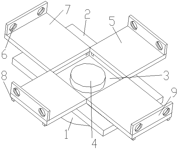
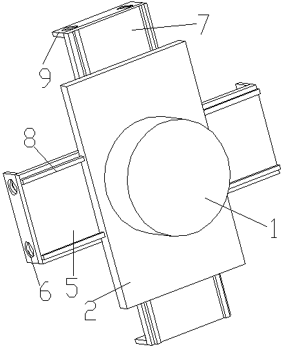
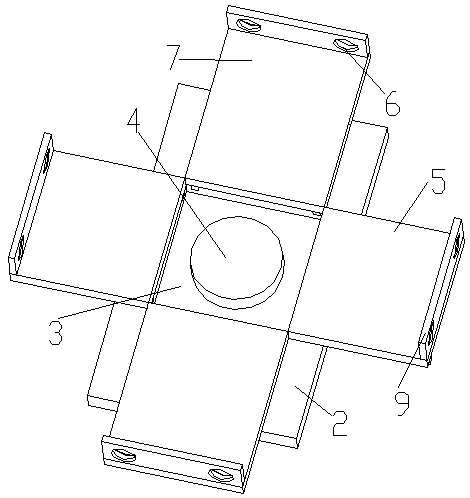
[0021] Such as figure 1 , figure 2 , image 3 and Figure 4 A movable charging pile shown includes a base plate, a rotating platform, a stretching plate part, a heat sink and a buffer part; one end of the rotating platform is fixedly connected to the base plate, and the other end is set on the ground, and the stretching plate part includes a t...


PUM


Abstract

The invention relates to the technical field of charging pile installation, in particular to a charging pile. The charging pile comprises a base plate, a rotating platform, a stretching plate part, aheat dissipation groove and a buffer part. The base plate is arranged on the rotating platform, and the base plate can be rotated by 360 degrees, so that the problem of winding or inconvenient charging caused by inconvenient rotation of the charging pile is solved. The stretching plate part is arranged on the base plate, the flexible change of the length of an installation plate in four directionsis realized, and the installation requirements of more types of charging piles are met. The structure is simple, and the operation is convenient. The heat dissipation groove is formed on the center of the installation plate, so that it is guaranteed that the heat dissipated by the charging pile during working is dissipated through the heat dissipation groove, and the safety is improved. The buffer part is arranged in the heat dissipation groove, so that the charging pile is better protected and is prevented from damage caused by the impact force. The charging pile has simple structure, convenient installation, flexibility and changeability, higher safety performance, wider application range and high practicability.

Description

technical field [0001] The invention relates to the technical field of charging pile installation, in particular to a movable charging pile. Background technique [0002] The function of the charging pile is similar to the refueling machine in the gas station. It can be fixed on the ground or wall, and installed in the parking lot or charging station of public buildings and residential areas. It can charge various types of electric vehicles according to different voltage levels. The input end of the charging pile is directly connected to the AC grid, and the output end is equipped with a charging plug for charging the electric vehicle. Charging piles generally provide two charging methods: conventional charging and fast charging. People can use a specific charging card to swipe the card on the human-computer interaction interface provided by the charging pile to perform corresponding charging methods, charging time, and cost data printing. The display screen of the charging...

Claims


Application Information

Patent Timeline
Patent Type & Authority Patents(China)
IPC IPC(8): B60L11/18
CPCB60L53/30B60L53/31Y02T10/70Y02T10/7072Y02T90/12
Inventor 任祥生
Owner 重庆荣渝创新信息技术有限责任公司
Why Eureka
Try Eureka