Supercharge Your Innovation With Domain-Expert AI Agents!

Method and system for realizing accurate positioning of locomotives through station detection area

An accurate positioning and detection area technology, applied in railway signaling and safety, etc., can solve problems such as inaccurate operation status and inability to meet practical application requirements, and achieve the effect of improving on-site management efficiency

Active Publication Date: 2019-03-01
CHONGQING MICRO IDENTIFICATION TECH
View PDF9 Cites 0 Cited by
  • Summary
  • Abstract
  • Description
  • Claims
  • Application Information

AI Technical Summary

Problems solved by technology

[0003] In view of the shortcomings of the prior art described above, the purpose of the present invention is to provide a method and system for accurate positioning of locomotives passing through the station inspection area, which is used to solve the problem of using magnetic steel to locate locomotives in the station yard in the prior art. The running state is not accurate enough and cannot meet the actual application requirements

Method used


Image

  • Method and system for realizing accurate positioning of locomotives through station detection area
  • Method and system for realizing accurate positioning of locomotives through station detection area
  • Method and system for realizing accurate positioning of locomotives through station detection area

Examples


Embodiment 1

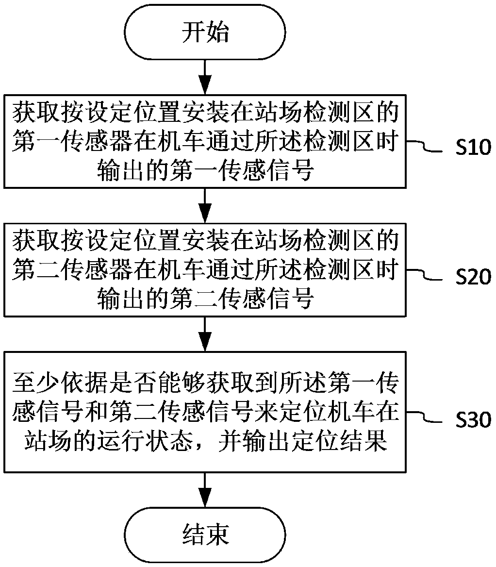
[0031] See figure 1 , the present embodiment 1 provides a method for allowing the locomotive to pass through the station detection area to achieve accurate positioning, and the implementation steps of the method include:

[0032] S10, acquiring a first sensing signal output by a first sensor installed in a station yard detection area according to a set position when a locomotive passes through the detection area;

[0033] S20, acquiring a second sensing signal output by a second sensor installed in the detection area of ​​the station according to the set position when the locomotive passes through the detection area;

[0034] S30, locating the running state of the locomotive at the station based at least on whether the first sensing signal and the second sensing signal can be obtained, and outputting a positioning result.

[0035] In a specific implementation, the detection area in step S10 refers to a broad area where passing signals are acquired (the same is true for step S...

Embodiment 2

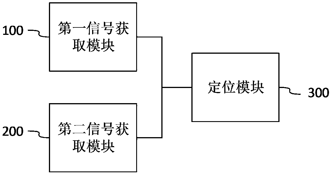
[0050] See figure 2 , the present embodiment provides a system for allowing locomotives to pass through the station inspection area to achieve accurate positioning, the system includes: a first signal acquisition module 100, used to obtain the first signal installed in the station inspection area according to a set position The first sensing signal output by the sensor when the locomotive passes through the detection area; the second signal acquisition module 200 is used to obtain the output of the second sensor installed in the detection area of ​​the station according to the set position when the locomotive passes through the detection area The second sensing signal; the positioning module 300, configured to locate the running state of the locomotive at the station based at least on whether the first sensing signal and the second sensing signal can be obtained, and output the positioning result.

[0051] The above-mentioned system uses the first signal acquisition module 10...


PUM


Abstract

The invention provides a method and a system for realizing accurate positioning by enabling a locomotive to pass through a station yard detection area and applies to the technical field of railway yard management. The method comprises the following steps: obtaining a first sensing signal output by a first sensor mounted in a set position of the station yard detection area when the locomotive passes through the detection area; obtaining a second sensing signal output by a second sensor mounted in a set position of the station yard detection area when the locomotive passes through the detection area; positioning the running state of the locomotive in a station yard at least according to whether the first sensing signal and the second sensing signal can be obtained, and outputting a positioning result. Starting from the site environment of the locomotive, one simple and effective locomotive positioning method is provided, and the site management efficiency of the station yard is increased.

Description

technical field [0001] The invention relates to the station yard management technology in the railway, in particular to a method and system for realizing accurate positioning by allowing locomotives to pass through the station yard detection area. Background technique [0002] With the information construction of the locomotive maintenance system, the accuracy of locomotive positioning in the maintenance station is getting higher and higher, and the running characteristics of the locomotive in the maintenance station are non-uniform speed, frequent parking, and frequent reversing. The way of positioning the locomotive by passive magnets (also called wheel sensors, hereinafter collectively referred to as: passive magnets) cannot meet the requirements of practical applications. In particular, due to the characteristics of the passive magnetic steel, it is difficult to accurately judge the running state of the locomotive through the passive magnetic steel at low speeds, so it n...

Claims


Application Information

Patent Timeline
Patent Type & Authority Patents(China)
IPC IPC(8): B61L25/02
CPCB61L25/02
Inventor 段文彬胡冲王红渊王意波
Owner CHONGQING MICRO IDENTIFICATION TECH
Features
  • R&D
  • Intellectual Property
  • Life Sciences
  • Materials
  • Tech Scout
  • Unparalleled Data Quality
  • Higher Quality Content
  • 60% Fewer Hallucinations
Learn More