
Battery car real-time monitoring system and method

A real-time monitoring, battery car technology, used in bicycle accessories, devices to prevent bicycle theft, transportation and packaging, etc., can solve the problems of inability to know the occurrence of theft, inability to track it, and easy to encounter theft.

Inactive Publication Date: 2017-01-04
SHANGHAI SHIBEI ELECTRONICS TECH
View PDF9 Cites 3 Cited by
  • Summary
  • Abstract
  • Description
  • Claims
  • Application Information

AI Technical Summary

Problems solved by technology

Due to the small size and light weight of the battery car, it is more convenient to carry, so it is prone to the risk of theft
The existing battery car anti-theft technology is usually to install a sensor on the battery car. When the battery car detects abnormal movements, it will send an alarm through the sound and light alarm device on the battery car. However, this alarm method has disadvantages: it acts as a reminder for the thief , and directly installed on the battery car, it is easy for the thief to use some means to avoid this alarm method; the alarm is only issued within a short distance, and if the owner is too far away, the occurrence of the theft still cannot be known; the vehicle is lost After that, it is impossible to track it, it is basically impossible to find it again, and it is difficult to find the thief; after the battery car is misoperated by the owner or others, it will trigger this kind of alarm, which is a kind of difficult for nearby people. Tolerated noise disturbance
[0003] To sum up, the existing anti-theft methods for battery cars are not smart enough and have many defects. Therefore, a battery car monitoring method with better anti-theft functions is needed

Method used


Image

  • Battery car real-time monitoring system and method
  • Battery car real-time monitoring system and method
  • Battery car real-time monitoring system and method

Examples


Embodiment Construction

[0036] In order to make the above objects, features and advantages of the present invention more comprehensible, specific implementations of the present invention will be described in detail below in conjunction with the accompanying drawings.

[0037] In the following description, numerous specific details are set forth in order to provide a thorough understanding of the present invention. However, the present invention can be implemented in many other ways different from those described here, and those skilled in the art can make similar extensions without violating the connotation of the present invention, so the present invention is not limited by the specific implementations disclosed below.

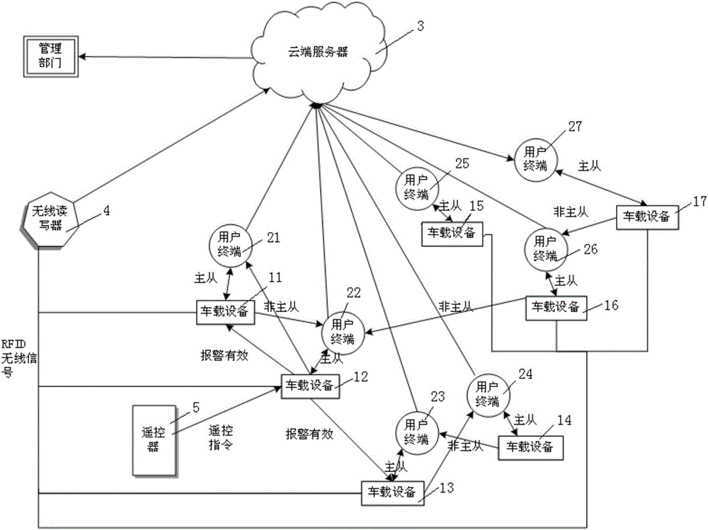
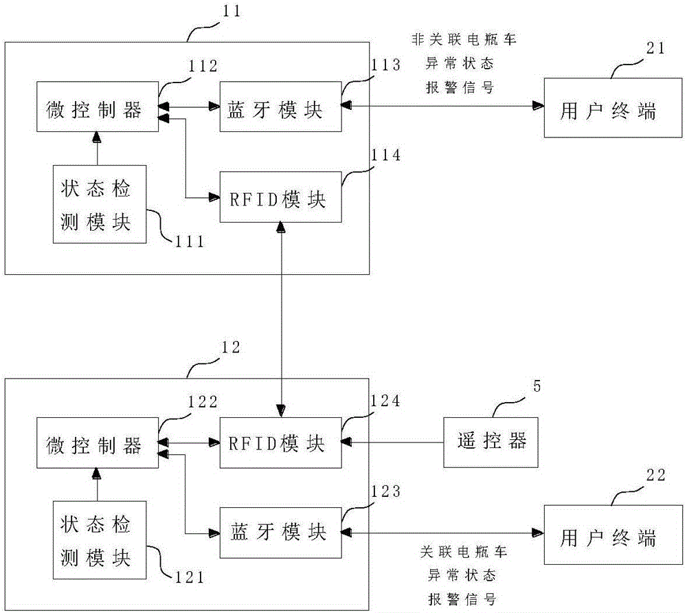
[0038] see figure 1 , the battery car real-time monitoring system of the embodiment of the present invention includes: a plurality of vehicle-mounted devices 11-17, a plurality of user terminals 21-27 and a cloud server 3. The user terminal can be a mobile phone, a tablet computer,...


PUM


Abstract

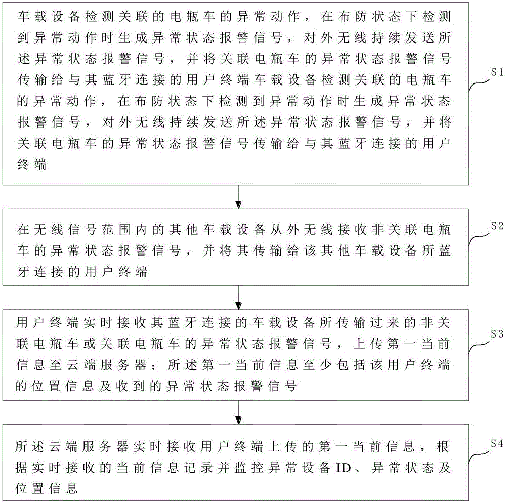
The invention provides a battery car real-time monitoring system and method. Each vehicle-mounted device is loaded on a battery car and used for detecting the abnormal actions of the battery car, generating and sending abnormal state alarm signals when detecting the abnormal actions in the deployment state, and transmitting the abnormal state alarm signals of the related battery car to a user terminal. Other vehicle-mounted devices in the wireless signal range wirelessly receive the abnormal state alarm signals of a non-related battery car from the outside and transmit the abnormal state alarm signals to user terminals in Bluetooth connection with other vehicle-mounted devices. The user terminals conduct instruction control on the Bluetooth connection vehicle-mounted devices and receive the abnormal state alarm signals, transmitted by the vehicle-mounted devices, of the non-related battery car or the related battery car in real time, and upload first current information to a cloud server. The cloud server receives the first current information uploaded by the user terminals in real time and records and monitors the ID, abnormal state and position information of an abnormal device according to the current information received in real time.

Description

technical field [0001] The invention relates to an anti-theft monitoring technology for a battery car, in particular to a real-time monitoring system and a monitoring method for a battery car. Background technique [0002] Electric vehicles, also known as electric vehicles, are faster than bicycles, more flexible and cheaper than cars, and have been widely popularized in recent years. Because the battery car is small in size and light in weight, it is more convenient to carry, so it is easy to encounter the risk of theft. The existing battery car anti-theft technology is usually to install a sensor on the battery car. When the battery car detects abnormal movements, it will send an alarm through the sound and light alarm device on the battery car. However, this alarm method has disadvantages: it acts as a reminder for the thief , and directly installed on the battery car, it is easy for the thief to use some means to avoid this alarm method; the alarm is only issued within ...

Claims


Application Information

Patent Timeline
Patent Type & Authority Applications(China)
IPC IPC(8): B62H5/20
CPCB62H5/20
Inventor 谢锋朱阅杨捷何晓军
Owner SHANGHAI SHIBEI ELECTRONICS TECH
Learn More