Vibrating drum with adjustable vibrating compacting force

An adjustable, vibrating wheel technology, applied in roads, road repairs, roads, etc., can solve problems such as inability to adapt, unfavorable compaction quality, etc.

Inactive Publication Date: 2017-01-04
青岛科泰重工机械有限公司
5 Cites 1 Cited by

AI-Extracted Technical Summary

Problems solved by technology

At present, the vibration mode of vibratory rollers at home and abroad is fixed in one form, and its compaction force remains unchanged from the beginning t...

Abstract

The invention provides a vibrating drum with adjustable vibrating compacting force. The vibrating drum comprises a drum body and a vibrating chamber, and the vibrating chamber is installed on the drum body through large bearing pedestals and supporting bearings and comprises a left vibrating chamber and a right vibrating chamber which are symmetrically arranged; a left vibrating shaft provided with a small eccentric block is installed in the left vibrating chamber through first large vibrating bearings, a right vibrating shaft provided with a small eccentric block is installed in the right vibrating chamber through second large vibrating bearings, and the left vibrating shaft and the right vibrating shaft are of the same structure and are connected through a middle vibrating shaft provided with a large eccentric block. By means of the mechanism, the vibrating modes of a vibrating roller can be conveniently and reliably switched, the compacting force can be automatically adjusted, and the different requirements of a compacted material for the compacting force in the initial stage of compacting and at the end of compacting can be met, so that the compacting quality is effectively improved; meanwhile, a foundation is laid for online intelligent control over vibrating parameters.

Application Domain

Roads maintainence

Technology Topic

EngineeringIntelligent control +1

Image

  • Vibrating drum with adjustable vibrating compacting force
  • Vibrating drum with adjustable vibrating compacting force
  • Vibrating drum with adjustable vibrating compacting force

Examples

  • Experimental program(1)

Example Embodiment

[0019] The technical solutions in the embodiments of the present invention will be clearly and completely described below in conjunction with the accompanying drawings in the embodiments of the present invention. Obviously, the described embodiments are only a part of the embodiments of the present invention, rather than all the embodiments. Based on the embodiments of the present invention, all other embodiments obtained by those of ordinary skill in the art without creative work shall fall within the protection scope of the present invention.
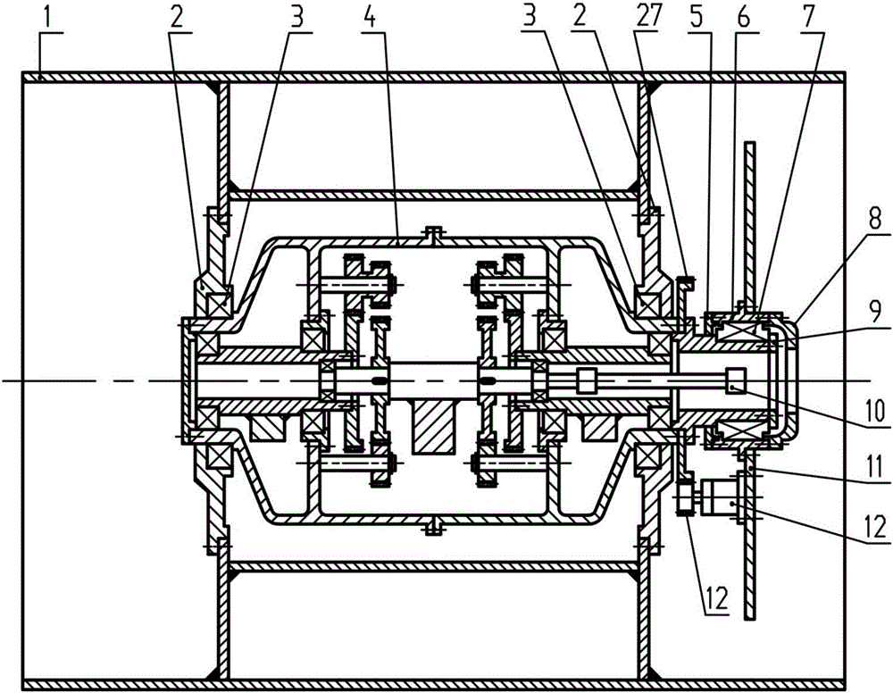
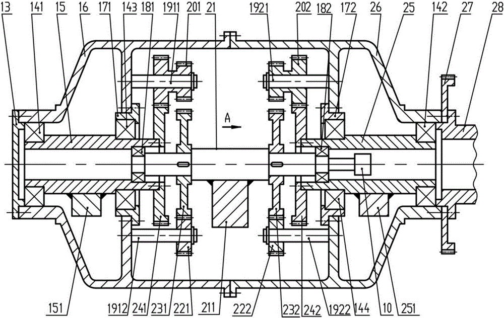
[0020] In the specific embodiment of the present invention, see Figure 1 ~ Figure 6 , A vibrating wheel with adjustable vibration pressure, including a wheel body 1 and a vibration chamber 4. The vibration chamber 4 is installed in the wheel body 1 through a large bearing seat 2 and a supporting bearing 3. The vibration chamber 4 includes a symmetrical left vibration chamber 16 and the right vibration chamber 26; the left vibration chamber 16 and the right vibration chamber 26 are each installed with a small eccentric block 151 and a small eccentric block 251 in the left vibration shaft 15 and the same structure through the large vibration bearing 141 and the large vibration bearing 142 The right vibrating shaft 25, the left vibrating shaft 15 and the right vibrating shaft 25 are connected by a middle vibrating shaft 21 provided with a large eccentric mass 2111; the left vibrating shaft 15 and the middle vibrating shaft 21, the middle vibrating shaft 21 and the right vibrating shaft 25 are connected It is driven by the left gear train and the right gear train arranged symmetrically; the gear train and the ring gear at both ends of the middle vibrating shaft 21 are used for transmission, and the number of teeth is matched to ensure the left vibrating shaft 15, the right vibrating shaft 25 and the middle vibrating shaft 21 Always have the same speed and opposite direction of rotation.
[0021] In the specific embodiment of the present invention, see figure 2 The sum of the static eccentricity of the small eccentric block 151 and the small eccentric block 251 is equal to the static eccentricity of the large eccentric block 2111. The symmetrical and coaxial arrangement of the three eccentric blocks is realized. The small eccentric block 151 and the small eccentric block 251 are The initial position of the large eccentric mass 2111 is the same and vertically downward; the left vibration shaft 15 and the right vibration shaft 25 have the same rotation direction, the left vibration shaft 15 and the right vibration shaft 25 and the middle vibration shaft 21 have opposite rotation directions, and the left vibration shaft 15, right The rotational speeds of the vibrating shaft 25 and the intermediate vibrating shaft 21 are the same.
[0022] In the specific embodiment of the present invention, see Figure 1 ~ Figure 2 , The outer end of the right vibrating shaft 25 is equipped with a drive gear 27 through the frame bearing inner seat 28. By driving the drive gear 27, the initial positions of the three eccentric blocks can be adjusted from vertical to horizontal. It can also be adjusted according to It is necessary to ensure that the initial positions of the three eccentric blocks are locked at any position from vertical to horizontal. The frame bearing inner seat 28 is fitted with an oil seal seat 5, and the frame bearing inner seat 28 is equipped with a frame bearing through the frame bearing 7 The outer seat 6, the frame bearing outer seat 6 is installed with a pressure plate 9 and a motor seat 8 from the inside to the outside. The pressure plate 9 has the function of fixing the frame bearing 7. A connecting plate 11 is installed on the frame bearing outer seat 6 and the connecting plate 11 is installed Hydraulic swing motor 12, the hydraulic swing motor 12 is connected with the soil stiffness detection integrated system, the hydraulic swing motor 12 is provided with a shaft end gear 121, the shaft end gear 121 meshes with the drive gear 27; when the hydraulic swing motor is installed on the connecting plate 11 12 When the intermediate vibrating shaft 21 rotates through the output power of the transition sleeve 10, the left vibrating shaft 15 and the right vibrating shaft 25 are driven to rotate in opposite directions at the same speed, so the resultant centrifugal force, namely the compressive force, is always the same as the initial pressure of the three eccentric blocks. The direction is the same. Therefore, as the hydraulic swing motor 12 drives the drive gear 27, the initial positions of the three eccentric blocks are gradually adjusted from vertical downwards to the horizontal direction, which realizes that the compaction force and vibration mode are changed from vertical vibration to vertical vibration. After the oblique vibration in the oblique direction is converted to the horizontal vibration in the horizontal direction, the mechanism can conveniently and reliably convert the vibration mode of the vibratory roller, realize the stepless adjustment and automatic control of the compaction strength, to adapt to the compacted material in the initial stage of compaction Compared with the different requirements on the compaction strength at the end of compaction, it effectively improves the compaction quality and lays the foundation for the online intelligent control of vibration parameters.
[0023] In the specific embodiment of the present invention, see Figure 1 ~ Figure 4 , The left vibrating shaft 15 is a hollow stepped shaft with a first stepped hole in the middle and thin at both ends, and the end of the stepped hole of the left vibrating shaft 15 with a smaller diameter is sleeved in the left vibrating chamber 16 through a large vibrating bearing 141, the same Therefore, the right vibrating shaft 25 is a hollow stepped shaft with a stepped hole in the middle and thin at both ends, and the stepped hole of the right vibrating shaft 25 is sleeved in the right vibrating chamber 26 through a large vibrating bearing 142; The shaft 21 includes an intermediate shaft 211 and a left end shaft 212 and a right end shaft 213 located on both sides of the intermediate shaft 211. The diameter of the left end shaft 212 and the right end shaft 213 is smaller than that of the intermediate shaft 211. The right end shaft 213 is also connected with a transition sleeve 10, and the left end shaft 212 is sleeved on the larger end of the stepped hole of the left vibrating shaft 15 via the first small vibrating bearing 181. Similarly, the right end shaft 213 is sleeved on the larger end of the stepped hole of the right vibrating shaft 25 via the second small vibrating bearing 182. .
[0024] In the specific embodiment of the present invention, see Figure 1 ~ Figure 4 , The left gear train includes a first small bearing seat 171, a first upper gear shaft 1911, a first double gear 201, a first lower gear shaft 1912, a first small ring gear 231, a first large ring gear 241 and a first transition Gear 221, double gear 201 includes a first large gear 2011 and a first small gear 2012; the left vibration chamber 16 is provided with a positioning first annular support rib 301, the first small bearing seat 171 is sleeved on the first annular support Inside the rib 301, the left vibrating shaft 15 is sleeved in the first small bearing seat 171 through the large vibrating bearing 143; the first annular support rib 301 is symmetrically provided with a first upper gear shaft 1911 and a first lower gear shaft that are horizontally directed to the right 1912, the first double gear 201 is mounted on the first upper gear shaft 1911, the first transition gear 221 is mounted on the first lower gear shaft 1912, and the junction between the left end shaft 212 and the intermediate shaft 211 is provided on the left end shaft 212 The first keyway 2121 is installed with a first small gear ring 231, the first small gear ring 231 meshes with the first transition gear 221, the left end shaft 212 and the left vibrating shaft 15 are equipped with a first large ring gear 241, The large ring gear 241 meshes with the large gear 2011 on the first dual gear 201.
[0025] In the specific embodiment of the present invention, see Figure 1 ~ Figure 4 , The right gear train includes a second small bearing seat 172, a second upper gear shaft 1921, a second double gear 202, a second lower gear shaft 1922, a second small ring gear 232, a second large ring gear 242 and a second transition Gear 222, double gear 202 includes a second large gear 2021 and a second small gear 2022; the right vibration chamber 26 is provided with a positioning second annular support rib 302, the second small bearing seat 172 is sleeved on the second annular support Inside the rib 302, the right vibrating shaft 25 is sleeved in the second small bearing seat 172 through the large vibration bearing 144; the second annular support rib 302 is symmetrically provided with a second upper gear shaft 1921 and a second lower gear shaft that are horizontally directed to the right In 1922, the second double gear 202 is installed on the second upper gear shaft 1921, the second transition gear 222 is installed on the second lower gear shaft 1922, and the junction of the right end shaft 213 and the intermediate shaft 211 is provided on the right end shaft 213 The second keyway 2131 is installed with a second small gear ring 232, the second small gear ring 232 meshes with the second transition gear 222, the right end shaft 213 and the right vibrating shaft 25 are installed at the junction of the second large gear ring 242, The two large ring gears 242 mesh with the large gear 2021 on the second dual gear 202.
[0026] In the specific embodiment of the present invention, see figure 2 , Figure 5 In the view A, the meshing relationship between the small gear 2022, the large gear 2021, the transition gear 222, the small gear ring 232, and the large gear ring 242 is shown, and the matching of their teeth is appropriate and reasonable, ensuring the small gear ring 232 It has the same rotation speed and opposite rotation direction as the large ring gear 242.
[0027] In the specific embodiment of the present invention, see figure 1 , figure 2 , Image 6 ,in Figure 4 In the static state, it shows the principle of the vibration mode conversion and the automatic adjustment of the compression force when the initial positions of the three eccentric blocks are in the vertical, inclined and horizontal directions; the initial positions of the three eccentric blocks are the same and vertically downward, When the middle vibrating shaft 21 rotates, the left vibrating shaft 15 and the right vibrating shaft 25 simultaneously rotate at the same speed as the middle vibrating shaft 21, and the direction of rotation is opposite to the middle vibrating shaft 21, then the resultant force of the centrifugal force generated by the three eccentric masses is In the vertical direction, the effect is vertical vibration, so the wheel body 1 will produce the greatest pressure on the ground; when the hydraulic swing motor 12 is used to drive the drive gear 27 to rotate 90°, the left vibration chamber 16 and the right vibration chamber 26 make it All the internal parts rotate 90° around the axis of the middle vibrating shaft 21 at the same time, so the initial positions of the three eccentric blocks are in the horizontal direction. When the middle vibrating shaft 21 rotates, the left vibrating shaft 15 and the right vibrating shaft 25 are at the same time as the middle vibrating shaft. The vibrating shaft 21 rotates at the same speed, and the direction of rotation is opposite to that of the intermediate vibrating shaft 21, then the resultant force of the centrifugal force generated by the three eccentric masses is horizontal, and the effect is horizontal vibration, so the wheel body 1 will produce the least compressive force on the ground . Since the hydraulic swing motor 12 can be automatically controlled according to road conditions, when the drive adjustment gear 27 rotates to any angle between vertical and horizontal, the resultant force of the centrifugal force generated by the three eccentric masses is the tilt direction, and the effect is tilt vibration, thus changing The pressure of wheel 1 on the ground is reduced.
[0028] The above descriptions are only preferred embodiments of the present invention and are not intended to limit the present invention. Any modification, equivalent replacement, improvement, etc. made within the spirit and principle of the present invention shall be included in the present invention. Within the scope of protection.

PUM

no PUM

Description & Claims & Application Information

We can also present the details of the Description, Claims and Application information to help users get a comprehensive understanding of the technical details of the patent, such as background art, summary of invention, brief description of drawings, description of embodiments, and other original content. On the other hand, users can also determine the specific scope of protection of the technology through the list of claims; as well as understand the changes in the life cycle of the technology with the presentation of the patent timeline. Login to view more.
Why Eureka
Try Eureka