A heater and its installation structure

An installation structure and technology for heaters, which are applied in the directions of household heating, lighting and heating equipment, and household heating, etc., can solve the problems of insufficient installation space and insufficient installation space for heaters.

Active Publication Date: 2018-04-20
GREE ELECTRIC APPLIANCES INC
View PDF8 Cites 0 Cited by
  • Summary
  • Abstract
  • Description
  • Claims
  • Application Information

AI Technical Summary

Problems solved by technology

In this way, the problem of insufficient installation space is caused
[0005] Therefore, how to solve the problem of insufficient installation space of the heater due to the different pre-embedded positions of the water pipes in the prior art has become an important technical problem to be solved by those skilled in the art.

Method used


Image

  • A heater and its installation structure
  • A heater and its installation structure
  • A heater and its installation structure

Examples


Embodiment Construction

[0022] The purpose of this specific embodiment is to provide a heater installation structure, which can solve the problem of insufficient installation space of the heater due to the different pre-embedded positions of the water pipes. Another object of this specific embodiment is to provide a heater including the above installation structure.

[0023] Hereinafter, an embodiment will be described with reference to the drawings. In addition, the examples shown below do not limit the content of the invention described in the claims in any way. In addition, all the contents of the configurations shown in the following embodiments are not limited to be essential to the solution of the invention described in the claims.

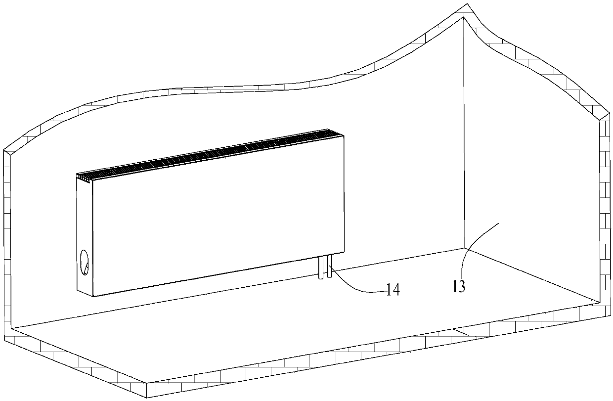
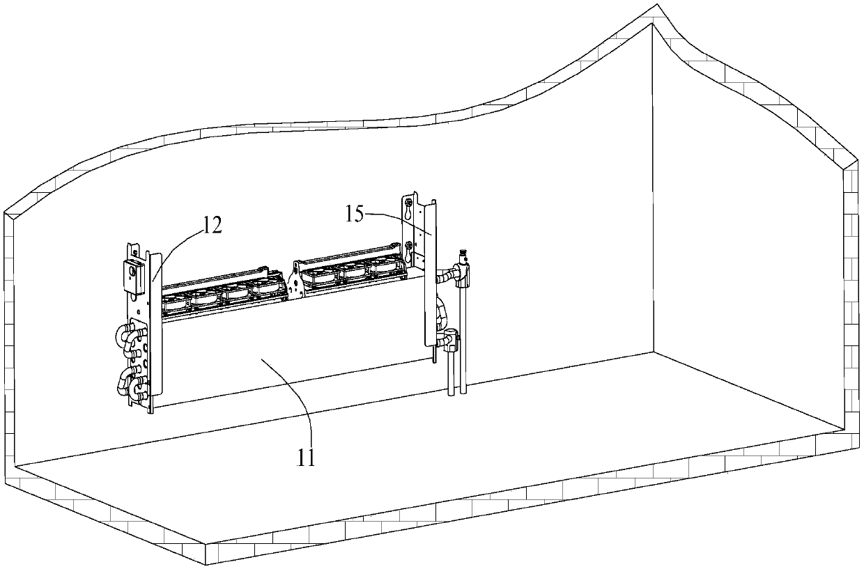
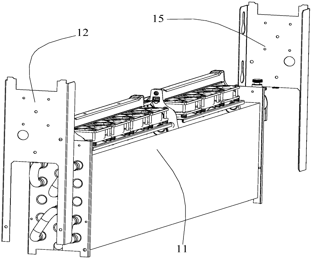
[0024] Please refer to Figure 1-Figure 3 , a heater installation structure provided in this specific embodiment includes a heat exchanger 11 and a first fixing plate 12, wherein the first fixing plate 12 is used to be fixedly connected to the wall, and the heat ...


PUM


Abstract

The invention discloses a warmer and a mounting structure thereof. The mounting structure comprises a heat exchanger and a first fixing plate used for fixing the heat exchanger to a wall. The heat exchanger is provided with a first connecting part and a second connecting part, and the first connecting part and the second connecting part can be connected with the first fixing plate. When the heat exchanger is in a first state, the first fixing plate can be connected with the first connecting part, and when the heat exchanger is in a second state, the first fixing plate can be connected with the second connecting part. According to the first state, the left side and the right side of the heat exchanger are not reversed, and according to the second state, the left side and the right side of the heat exchanger are reversed. Through the arrangement, by means of the mounting structure of the warmer, the problem that the mounting space for the warmer is insufficient due to different pre-burying positions of water tubes can be solved.

Description

technical field [0001] The invention relates to the technical field of heating equipment, more specifically, to a heater and its installation structure. Background technique [0002] In the prior art, the heat exchanger of the heater is mostly made of cast iron, and hot water or hot steam enters the heat exchanger, and the indoor ambient temperature is increased through heat radiation. [0003] In the prior art, the heater is installed on the wall, and the water pipes for providing hot water are pre-embedded on the bottom surface of the room. Since the spatial layout of each room is different, the pre-embedded positions of the water pipes are also different. Like this, when installing heater, may cause the problem of insufficient installation space. [0004] For example, the interface of the heater is arranged near the left side of the heater, and the distance between the embedded position of the water pipe and the wall on the left is smaller than the distance between the i...

Claims


Application Information

Patent Timeline
Patent Type & Authority Patents(China)
IPC IPC(8): F24D19/02
CPCF24D19/0209F24D19/023
Inventor 薛寒冬谢有富邓朝胜
Owner GREE ELECTRIC APPLIANCES INC
Why Eureka
Try Eureka