A step-frequency controllable gain receiver front-end for well radar

A receiver front-end, stepping frequency technology, used in radio wave measurement systems, instruments, etc., can solve the problem that it is difficult for radar to take into account high resolution and long detection distance, and achieve convenient gain control, high gain flatness, The effect of suppressing the interference of noise

Inactive Publication Date: 2019-04-05
UNIV OF ELECTRONICS SCI & TECH OF CHINA
View PDF6 Cites 0 Cited by
  • Summary
  • Abstract
  • Description
  • Claims
  • Application Information

AI Technical Summary

Problems solved by technology

[0003] At present, the vast majority of drilling radars belong to the shock pulse system, but it is difficult for this radar to meet the requirements of high resolution and long detection distance, and the corresponding frequency domain step frequency pulse radar can achieve high resolution High rate and high detection distance requirements, the system radar transmits high-power ultra-wideband small-step frequency signals, when encountering an underground medium with discontinuous electromagnetic properties, its reflection characteristics or transmission characteristics change, and finally from the reflected wave or Extract target information through pulse pressure technology in transmission waveform

Method used


Image

  • A step-frequency controllable gain receiver front-end for well radar
  • A step-frequency controllable gain receiver front-end for well radar
  • A step-frequency controllable gain receiver front-end for well radar

Examples


Embodiment Construction

[0024] The present invention will be further described in detail below in conjunction with the accompanying drawings and embodiments.

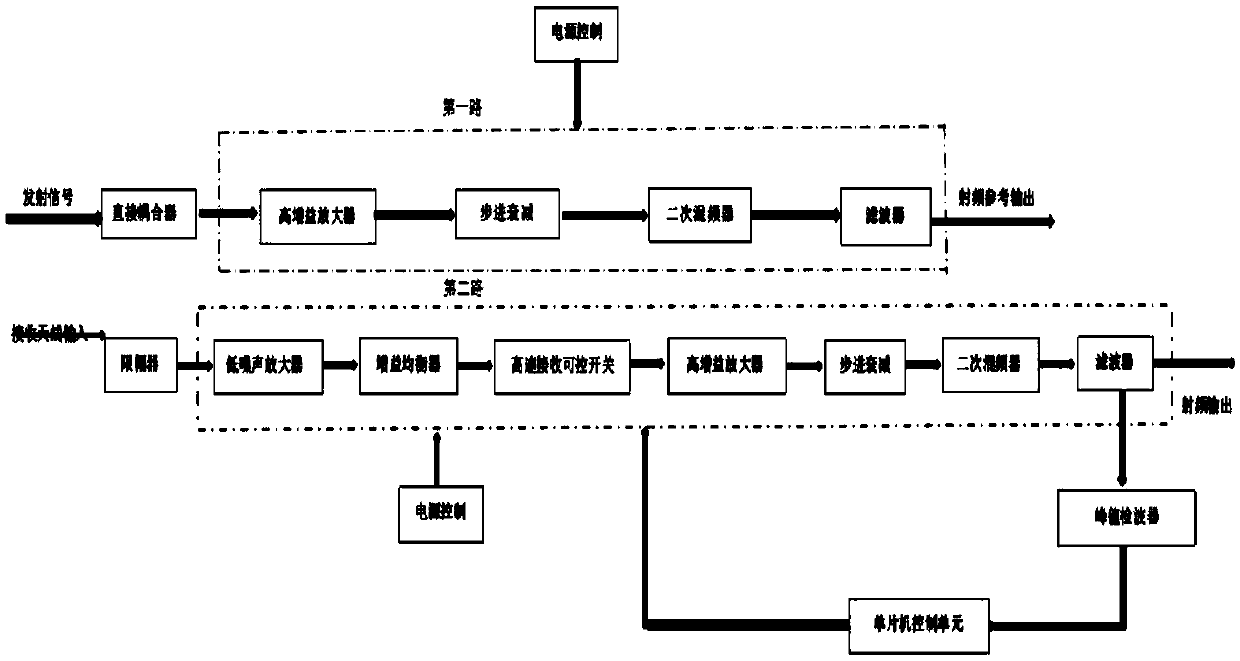
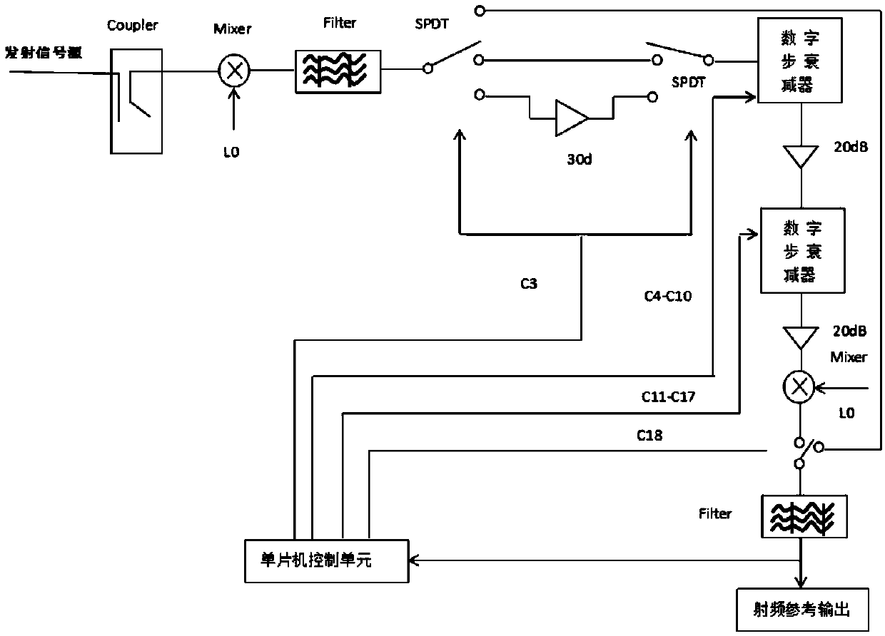
[0025] Such as figure 2 Shown is the design diagram of the first receiver front-end system of the embodiment.

[0026] This way is to directly collect the transmitted signal, and the circuit is output after two times of mixing, filtering and gain amplification. Because the signal acquisition of this channel and the signal acquisition of the second channel are carried out synchronously, the output signal of this channel is finally used as the reference signal of the second channel, so that the subsequent processing unit can calculate the transfer of the system through phase comparison and amplitude comparison. function.

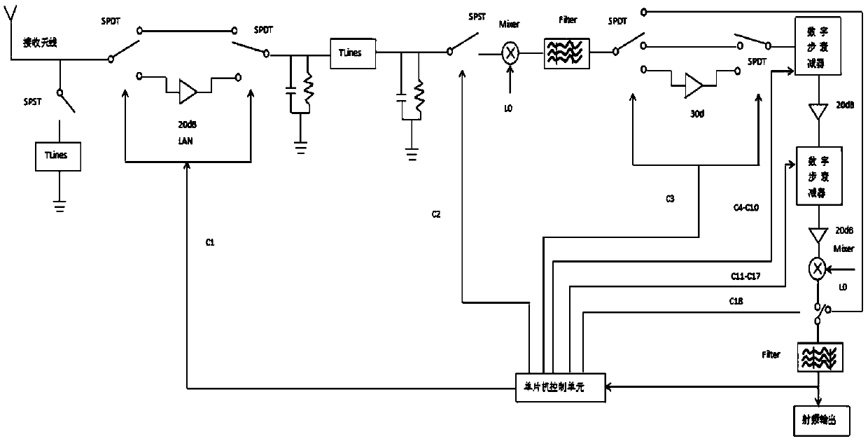
[0027] Such as image 3 Shown is the design diagram of the front-end system of the second receiver of the embodiment. The limiter is a low-noise limiter diode with 0.1db, which cuts the edge of the excessive signal, so as...


PUM


Abstract

The invention belongs to a hardware component unit of a well radar logging system, in particular to a front end of a well radar step frequency controllable gain receiver. The invention realizes the real-time adjustment and control of the gain step value through the single-chip microcomputer control circuit according to the magnitude of the final output signal, and provides a controllable gain control function of open and closed loops. The mixer and filter circuit have down-converted the input signal at least twice, so that the frequency bandwidth of the final output intermediate frequency signal is very narrow, and the instantaneous bandwidth corresponding to the receiver is very small, which effectively suppresses the noise interference and improves the system sensitivity. In the gain control unit, the use of the gain equalizer achieves high gain flatness, and finally provides a linear gain control of -13dB ~ 95dB, and a gain step of 0.5dB ~ 16dB. The invention realizes the asynchronous mode of sending and receiving, high gain flatness and convenient gain control; it is suitable for a receiver system with a large variation range of received signals.

Description

technical field [0001] The invention belongs to the hardware component unit of the radar well logging system in the well, and is mainly used to process the signal at the back end of the receiving antenna, and output the dual-channel radio frequency signal for the subsequent data acquisition unit, and specifically relates to a stepping frequency controllable gain receiver of the radar in the well front end. Background technique [0002] With the increasing demand of human beings for underground resources such as oil and gas, people's research on underground detection technology is increasing day by day. This requires in-depth research on resource distribution and geological structure, and the high cost of experiments urgently requires a high-precision, high-efficiency logging method. The borehole radar logging system is the product of applying borehole radar to petroleum logging. Its working mechanism is to detect geological anomalies with discontinuous electromagnetic chara...

Claims


Application Information

Patent Timeline
Patent Type & Authority Patents(China)
IPC IPC(8): G01S7/285G01S7/34
CPCG01S7/285G01S7/34
Inventor 赵青厉华洋霍建建马春光谢龙昊
Owner UNIV OF ELECTRONICS SCI & TECH OF CHINA
Why Eureka
Try Eureka