Permanent magnet spherical motor point-to-point motion track planning method based on sine acceleration function and application thereof

A technology of sinusoidal acceleration and spherical motors, applied in general control systems, instruments, simulators, etc., can solve the problem of not considering the adverse effects of input signal control objects, and achieve the effect of reducing peak value and simple expression

Active Publication Date: 2017-01-04
ANHUI UNIVERSITY
View PDF5 Cites 11 Cited by
  • Summary
  • Abstract
  • Description
  • Claims
  • Application Information

AI Technical Summary

Problems solved by technology

However, it does not take into account the possible ad

Method used


Image

  • Permanent magnet spherical motor point-to-point motion track planning method based on sine acceleration function and application thereof
  • Permanent magnet spherical motor point-to-point motion track planning method based on sine acceleration function and application thereof
  • Permanent magnet spherical motor point-to-point motion track planning method based on sine acceleration function and application thereof

Examples


Embodiment 1

[0104] Embodiment 1: Similar spiral motion trajectory planning

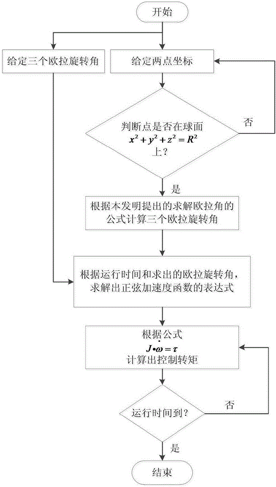
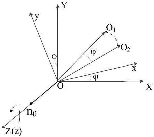
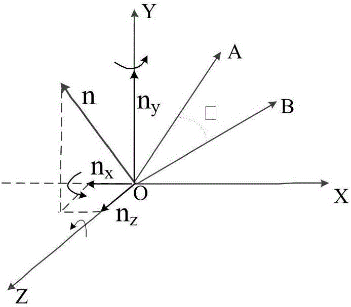
[0105] Such as Figure 8a , select a total of 7 key points of the spiral curve A0-A6 on the spherical surface, the top of the rotor output shaft starts from the starting point A0, and then arrives at A1, A2, A3, A4, A5, A6, and its coordinates are shown in Table 4. Solving according to formula (4) obtains 3 Euler rotation angles between adjacent two points, then utilizes the present invention to propose the permanent magnet spherical motor trajectory planning method based on sinusoidal acceleration function, stipulates that the motion time between every adjacent point is 1 seconds, and then solve the function expression of the sinusoidal acceleration corresponding to the X, Y, and Z directions by formula (11), and finally get the function expression of the control torque according to formula (13). Since the movement of each circle of the helical motion is similar to a circle, the expression of the torque is slig...

Embodiment 2

[0108] Embodiment 2: Writing of the trajectory of the initial letter AHU of Anhui University

[0109] Such as Figure 9a , select 17 key points of the AHU letter on the spherical surface, start from the starting point B0, pass through B1-B16 in turn, and finally return to the starting point B0, and solve the three Euler rotations between two adjacent points according to formula (4) Angle, then use the present invention to propose the permanent magnet spherical motor trajectory planning method based on the sinusoidal acceleration function, stipulate that the motion time between each adjacent connection point is 1 second, then solve the sine corresponding to the X, Y, Z directions by formula (11) Acceleration function expression, and finally according to the formula (13) can get the function expression of the control torque. In the Adams software, the torque is expressed in the form of if function, and the simulation time is set to 17 seconds, and the step size is 850. After th...


PUM


Abstract

The invention discloses a permanent magnet spherical motor point-to-point motion track planning method based on a sine acceleration function and application thereof. The method is characterized in that a permanent magnet spherical motor rotor is regarded as a research object, firstly a Euler rotation angle or coordinates of two points are given, and the Euler rotation angle is inversely solved by adopting a method of reversely solving the Euler rotation angle according to the coordinates of the two points; then, an expression of the sine acceleration function is solved according to the operating time and initial conditions, and finally a final control torque is obtained according to a rotor dynamics equation. By the adoption of the method, permanent magnet spherical motor point-to-point motion track planning is achieved, the method is applied to complicated and continuous track planning, the adverse influence of input signal impact, non-continuous change and other factors on a control object can be effectively reduced, and accordingly the control accuracy of a control system and the stability of motor operation are improved.

Description

technical field [0001] The invention relates to a trajectory planning method for three-degree-of-freedom motion in three-dimensional space, in particular to a trajectory planning method for point-to-point motion in three-dimensional space for a permanent magnet spherical motor by using a sinusoidal acceleration function and its application. Background technique [0002] With the continuous development of modern industrialization and informatization, motors that can realize multi-degree-of-freedom motion are favored by many scholars. Spherical motors have bright application prospects. In space three-dimensional motion systems such as robot joints, manipulators, panoramic camera systems, and satellite attitude control systems, spherical motors can not only replace traditional combined motors to complete three-dimensional space motions, but also greatly simplify their mechanisms. Improve the control accuracy, reduce the size, and achieve the purpose of fast positioning. [000...

Claims


Application Information

Patent Timeline
IPC IPC(8): G05B17/02
CPCG05B17/02
Inventor 过希文李绅王群京文彦赵丽娟吴玉良
Owner ANHUI UNIVERSITY
Why Eureka
Try Eureka