
Improved indoor return machine

An improved, book machine technology, applied in the direction of cash registers, instruments, etc., can solve the problems of book damage, increase the difficulty and trouble of installation, and achieve the effects of slow falling, loss prevention and damage reduction.

Active Publication Date: 2019-01-15
JIANGSU SENSEIT ELECTRONICS TECH
View PDF7 Cites 0 Cited by
  • Summary
  • Abstract
  • Description
  • Claims
  • Application Information

AI Technical Summary

Problems solved by technology

However, the scanning head of the existing indoor book returning machine is fixed and cannot be adjusted, so that the position of the scanning head cannot be adjusted during installation and debugging. When the position of the scanning head cannot adapt to the position of the lower conveyor belt, the It is very troublesome to re-modify the conveyor belt or the fixed parts of the scanning head, which increases the difficulty of installation, and when returning the book, the barcode is generally installed in the book, and the front page of the book needs to be turned over. The book can only be returned after scanning the barcode under the scanning head, which requires the book returner to turn over the front page, and then need to compact the front page of the book after scanning, which is very troublesome
[0003] Moreover, the book collection box on the existing indoor book return machine is generally a rectangular body, and the books are directly dropped on the bottom plate of the book collection box after being scanned. Because it is directly dropped on the bottom plate, it is easy to damage the book. , affecting the service life

Method used


Image

  • Improved indoor return machine
  • Improved indoor return machine
  • Improved indoor return machine

Examples


Embodiment Construction

[0034] The present invention will be described in detail below in conjunction with accompanying drawings and specific preferred embodiments, so that the advantages and features of the present invention can be more easily understood by those skilled in the art. range is limited.

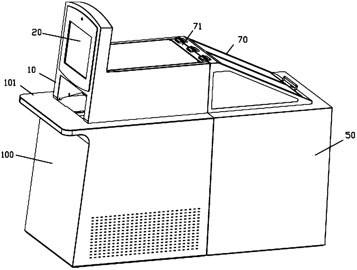
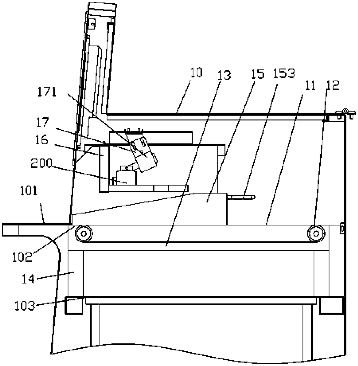
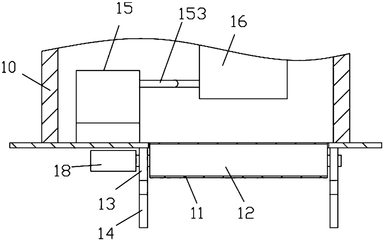
[0035] Examples, see e.g. Figures 1 to 14 As shown, an improved indoor book return machine includes a book return machine box 100 and a box body 50, an upper support body 10 is fixed on the upper horizontal plate 101 of the book return machine box body 100, and the top surface of the upper support body 10 A liquid crystal display 20 is fixed on it, the box body 50 is behind the book returning machine box body 100, the front side plate of the box body 50 is pressed against the rear wall surface of the book returning machine box body 100, and the protective cover 70 covered above the box body 50 The front end of the front end is hinged with a connecting plate 71, and the connecting plate 71 is fixed o...


PUM


Abstract

The invention discloses an improved indoor book return machine. The book return machine comprises a book return machine box body and a box body. The upper horizontal plate of the book return machine box body is fixedly provided with an upper supporting body, the top surface of which is fixedly provided with a liquid crystal display screen. The box body is disposed on the rear part of the book return machine box body, and the front side plate of the box body abuts against the rear wall surface of the book return machine box body. A front end of a protection cover disposed on the upper part of the box body in a covered manner is connected with a connecting plate by a hinge in a hinged manner, and the connecting plate is fixedly disposed on the top plate on the rear part of the upper supporting body. The lower part of the top plate of the upper supporting body is provided with a scanning head connecting plate, two ends of which are fixedly disposed on the two side walls of the upper supporting body. The improved indoor book return machine is advantageous in that during installation, a main connecting rod is adjusted, and then the position of the scanning head is corresponding to a position of a conveyor belt, and the scanning during subsequent book returning is facilitated; the box body is used to buffer the falling books, and the falling of the books is slow, and the damages of the books are reduced.

Description

Technical field: [0001] The invention relates to the technical field of self-service book return machine equipment, and more specifically relates to an improved indoor book return machine. Background technique: [0002] At present, domestic universities and government libraries mostly realize the management of books through bar codes and magnetic stripes. Use the barcode to identify the relevant information of the book, and the magnetic strip to ensure the safety of the book. Readers usually have to borrow and return books when library staff are on duty. In the case that the commuting time of readers and staff is almost synchronized, readers hope that they can return the borrowed books or borrow books in time after the library is closed or without entering the library. However, the scanning head of the existing indoor book returning machine is fixed and cannot be adjusted, so that the position of the scanning head cannot be adjusted during installation and debugging. When ...

Claims


Application Information

Patent Timeline
Patent Type & Authority Patents(China)
IPC IPC(8): G07G1/00
Inventor 沙军
Owner JIANGSU SENSEIT ELECTRONICS TECH
Learn More