Antenna Structure And Wireless Communication Device Using The Same

A technology of wireless communication device and antenna structure, which is applied to devices, antenna supports/installation devices, antennas and other directions that make antennas work in different frequency bands at the same time, which can solve the problem of poor radiation performance of built-in antennas, difficult broadband design, and easy interference. Signal and other problems, to avoid shielding effect, reduce the size and space of the antenna, and reduce the cost

Inactive Publication Date: 2017-01-04
SHENZHEN FUTAIHONG PRECISION IND CO LTD +1
View PDF7 Cites 5 Cited by
  • Summary
  • Abstract
  • Description
  • Claims
  • Application Information

AI Technical Summary

Problems solved by technology

However, the metal shell is easy to interfere with the signal radiated by the antenna installed in it, and it is not easy to achieve broadband design, resulting in poor radiation performance of the built-in antenna

Method used


Image

  • Antenna Structure And Wireless Communication Device Using The Same
  • Antenna Structure And Wireless Communication Device Using The Same
  • Antenna Structure And Wireless Communication Device Using The Same

Examples


Embodiment Construction

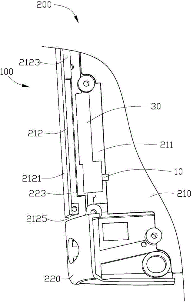
[0018] see figure 1 , The first preferred embodiment of the present invention provides an antenna structure 100, which is applied in wireless communication devices 200 such as mobile phones, tablet computers or smart watches, for transmitting and receiving radio waves to transmit and exchange wireless signals. The wireless communication device 200 further includes a substrate 210 and a metal casing 220 disposed around the substrate 210 .

[0019] The substrate 210 can be a printed circuit board (Printed Circuit Board, PCB). A clearance zone 211 is set on the substrate 210, and the clearance zone 211 is located below the radiator 30 of the antenna structure 100. The clearance zone 211 refers to an area where no conductor exists on the substrate 210, and is used to prevent electronic components such as batteries from being exposed to the external environment. , a vibrator, a horn, a CCD (Charge Coupled Device, charge coupled device), etc. interfere with the antenna structure 10...


PUM


Abstract

The present invention relates to an antenna structure and a wireless communication device using the same. The wireless communication device includes a metallic housing and an antenna structure. The antenna structure includes a feed end and a radiator. The radiator is connected to the feed end and extends towards the metallic housing. The metallic housing defines a gap between the metallic housing and the radiator for coupling the metallic housing with the radiator through electromagnetic induction. A size of the gap is determined by a wavelength of wireless signals received or transmitted by the wireless communication device. The radiator and the metallic housing cooperatively resonate in at least two modes. The metallic housing of the present invention is equipped with the gap, so that the metallic housing forms a part of the antenna structure, a shielding effect caused by the metallic housing to an antenna is avoided, the size of the antenna and the occupation space are reduced, and an effect of reducing cost is realized.

Description

technical field [0001] The invention relates to an antenna structure and a wireless communication device using the antenna structure. Background technique [0002] With the advancement of wireless communication technology, wireless communication devices are constantly developing towards a thinner and lighter trend, and consumers have higher and higher requirements for product appearance. Since metal shells have advantages in appearance, structural strength, heat dissipation effect, etc., more and more manufacturers design wireless communication devices with metal shells to meet the needs of consumers. However, the metal shell easily interferes and shields the signal radiated by the antenna disposed therein, and it is not easy to achieve broadband design, resulting in poor radiation performance of the built-in antenna. Moreover, with the continuous development of Long Term Evolution (LTE) technology, the bandwidth of the antenna continues to increase. Therefore, how to desi...

Claims


Application Information

Patent Timeline
Patent Type & Authority Applications(China)
IPC IPC(8): H01Q1/22H01Q17/00
CPCH01Q9/40H01Q9/42H01Q13/10H01Q5/357H01Q5/371H01Q1/243
Inventor 李义杰林彦辉
Owner SHENZHEN FUTAIHONG PRECISION IND CO LTD
Why Eureka
Try Eureka