
Method and apparatus for realizing switching

A technology for controlling signals and circuits, applied to circuit devices, electrical components, emergency power supply arrangements, etc., can solve problems such as output voltage rise and repeated startup of electronic equipment, and achieve the effect of avoiding repeated startup

Inactive Publication Date: 2017-01-04
ZTE CORP
View PDF7 Cites 0 Cited by
  • Summary
  • Abstract
  • Description
  • Claims
  • Application Information

AI Technical Summary

Problems solved by technology

[0004] In the existing switching circuit, when the electronic device is automatically shut down at the end of the battery life, the output voltage of the battery will rise due to the load reduction, resulting in the so-called "recycle" phenomenon, which will cause the electronic device to enter a power-off-power-off state. Electric cycle, that is, repeated power-on, resulting in repeated power-on of electronic equipment

Method used


Image

  • Method and apparatus for realizing switching
  • Method and apparatus for realizing switching
  • Method and apparatus for realizing switching

Examples


no. 1 example

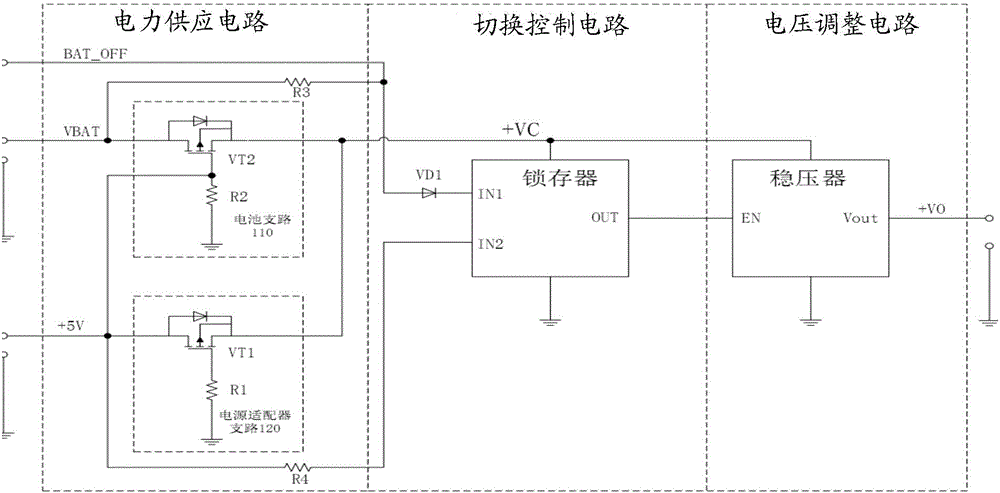
[0072] For a first example, see image 3 , the device at least includes: a control interface (that is, BAT_OFF in the figure), a power supply circuit, a switching control circuit and a voltage adjustment circuit.

[0073] The power supply circuit includes a battery branch 110 and an AC power adapter branch 120 . The battery branch 110 includes a PMOS VT2, and the AC power adapter branch 120 includes a PMOS VT1. The gate of PMOS VT2 is grounded through resistor R2, the drain of PMOS VT2 is connected to the positive pole of the battery, the source of PMOS VT2 is connected to the source of PMOS VT1, the gate of PMOS VT1 is grounded through resistor R1, and the drain of PMOS VT1 is connected to the source of PMOS VT1. Connect to the positive terminal of the AC power adapter.

[0074] When only the battery is in place, the PMOS VT2 is turned on and the PMOS VT1 is turned off to provide power supply through the battery branch 110 . When the AC power adapter is in place, the PMOS ...

no. 2 example

[0077] For a second embodiment, see Figure 4 , the device includes at least:

[0078] Control interface (that is, BAT_OFF in the figure), power supply circuit, switching control circuit and voltage adjustment circuit.

[0079] The power supply circuit includes a battery branch 110 and an AC power adapter branch 120 . The battery branch 110 includes a PMOS VT2, and the AC power adapter branch 120 includes a PMOS VT1. The gate of PMOS VT2 is grounded through resistor R2, the drain of PMOS VT2 is connected to the positive pole of the battery, the source of PMOS VT2 is connected to the source of PMOS VT1, the gate of PMOS VT1 is grounded through resistor R1, and the drain of PMOS VT1 is connected to the source of PMOS VT1. Connect to the positive terminal of the AC power adapter.

[0080] Figure 4 Among them, +5V represents the output of the AC power adapter, and VBAT represents the output of the battery.

[0081] The switching control circuit uses an RS latch. The control...


PUM


Abstract

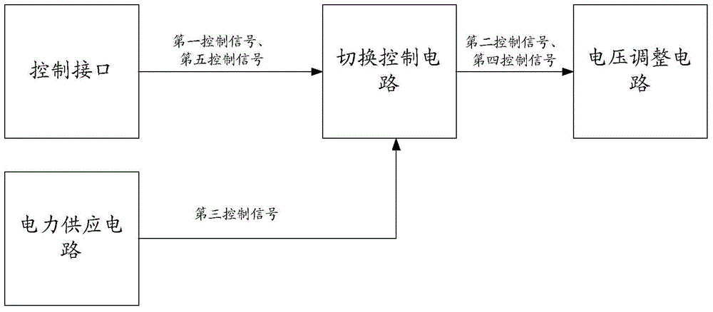
The invention discloses a method and apparatus for realizing switching. The apparatus at least comprises a control interface, a switching control circuit and a voltage adjusting circuit; the control interface is used for outputting first control signals to the switching control circuit when a main power source is not in place, and power outage is required; the switching control circuit is used for outputting second control signals to the voltage adjusting circuit according to the first control signals; and the voltage adjusting circuit is used for executing power outage operation according to the second control signals. With the method and apparatus provided by the technical schemes of the invention adopted, an electronic device can be prevented from entering a power off-power on-power off cycle.

Description

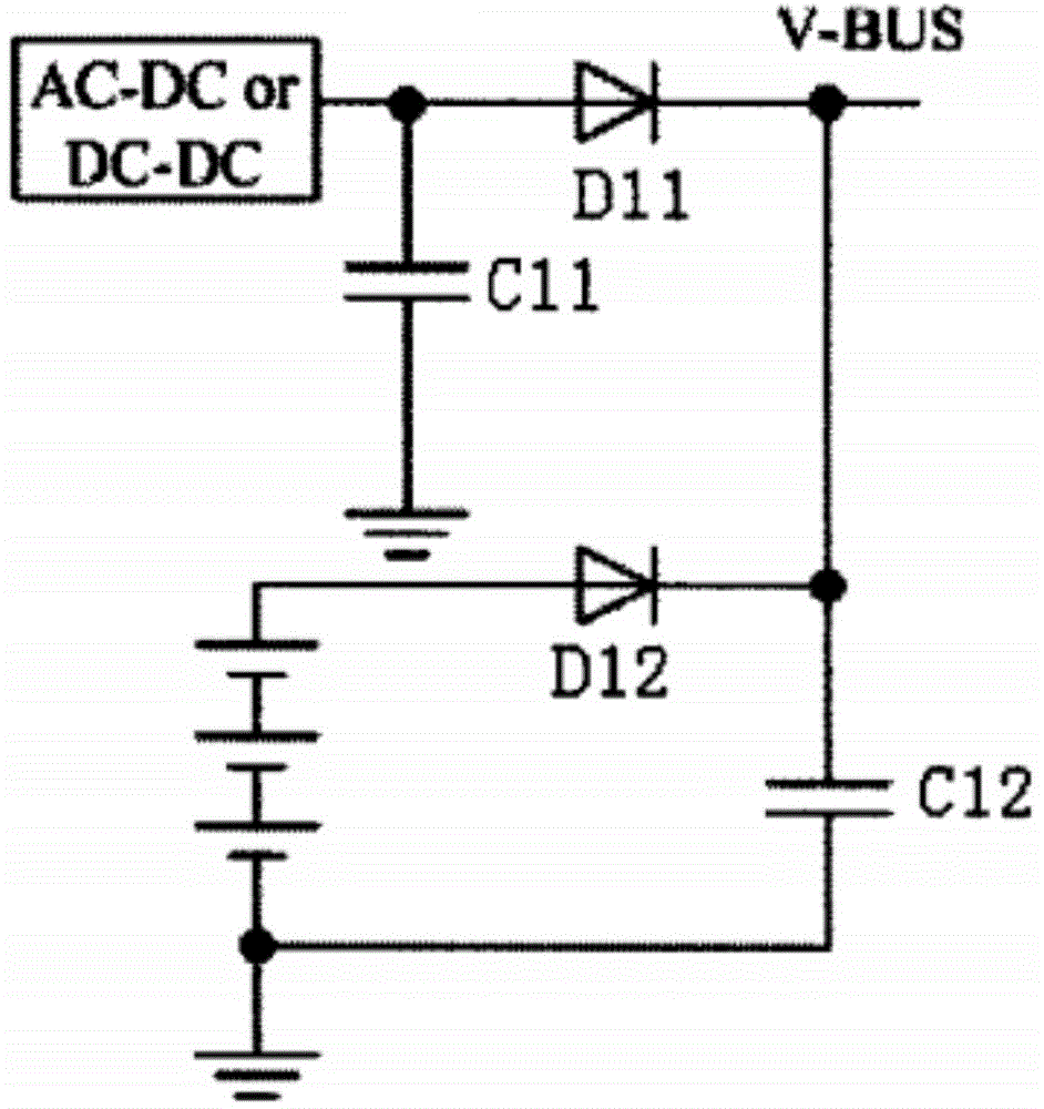
technical field [0001] The invention relates to the field of security protection, in particular to a method and device for realizing switching. Background technique [0002] In the field of security, electronic devices generally use batteries as backup power. When the main power supply (usually AC power adapter) is unexpectedly powered off, it will continue to provide security protection for a certain period of time, which is called battery life. Due to the characteristics of the application, the security equipment generally does not have a power switch button, and it starts to work when it is connected to the AC voltage, and it will automatically shut down when the battery is exhausted. [0003] figure 1 It is a schematic diagram of an existing switching circuit. Such as figure 1 As shown, metal-oxide-semiconductor field-effect transistors (MOSFET, Metal-Oxide-Semiconductor Field-Effect Transistor ) or diodes. When the AC power adapter of the main power branch is in pl...

Claims


Application Information

Patent Timeline
Patent Type & Authority Applications(China)
IPC IPC(8): H02J9/06
Inventor 王滔
Owner ZTE CORP
Learn More