
Computer system and power supply control device thereof

A technology of power control device and computer system, which is applied in the direction of measuring device, data processing power supply, measuring flow rate/mass flow rate, etc., can solve problems such as shortening the service life of the computer, and achieve the effect of avoiding repeated booting.

Inactive Publication Date: 2011-11-09
贵州聚控科技有限公司
View PDF0 Cites 0 Cited by
  • Summary
  • Abstract
  • Description
  • Claims
  • Application Information

AI Technical Summary

Problems solved by technology

[0006] In other words, the above two problems will cause the computer system to be forced to shut down after being turned on once, causing users to mistakenly think that the computer is damaged, or to shorten the service life of the computer by repeatedly turning on the computer

Method used


Image

  • Computer system and power supply control device thereof
  • Computer system and power supply control device thereof
  • Computer system and power supply control device thereof

Examples


Embodiment Construction

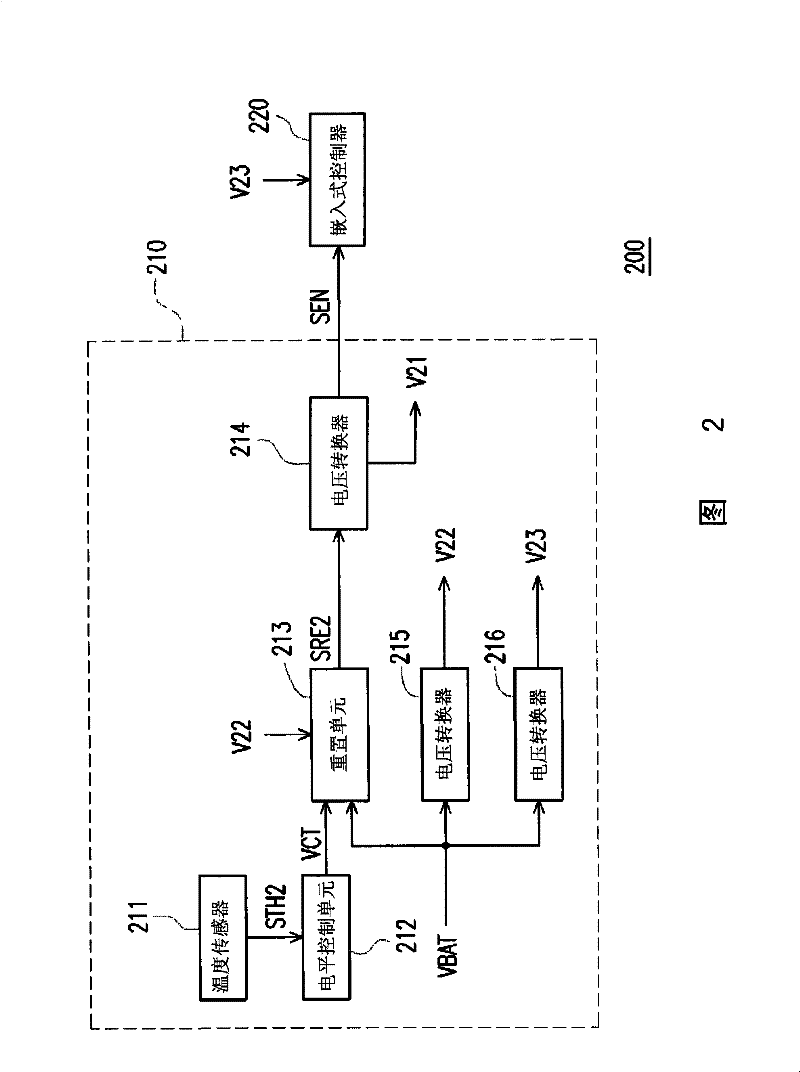
[0018] figure 2 Shown is a partial block diagram of a computer system according to an embodiment of the present invention. refer to figure 2 , the computer system 200 includes a power control device 210 and an embedded controller 220 . Wherein, the power control device 210 is electrically connected to the embedded controller 220, and is used to control the operation of the embedded controller 220, so that the computer system 200 can be turned on and off normally. During the boot process of the computer system 200, the temperature sensor 221 is enabled to operate normally after the embedded controller 210 operates normally.

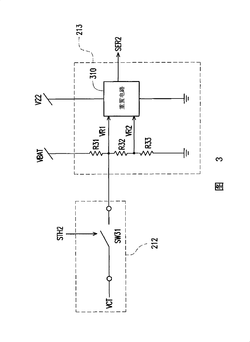
[0019] Further, the power control device 210 includes a temperature sensor 211 , a level control unit 212 , a reset unit 213 and a plurality of voltage converters 214 - 216 . Wherein, the level control unit 212 is electrically connected to the temperature sensor 211 and the reset unit 213 . The voltage converter 214 is electrically connected to the r...


PUM


Abstract

The invention discloses a computer system and a power supply control device thereof. The power supply control device comprises a temperature sensor, a level control unit, a reset unit and a first voltage converter. The temperature sensor is used for sensing working temperature of the computer system and outputting a sensing signal accordingly. The level control unit is used for determining whether to output control voltage according to the sensing signal. The reset unit is used for generating a reset signal according to a plurality of reference voltages generated by dividing power supply voltage and for regulating the level of the reference voltages by employing the control voltage. The first voltage converter is used for generating an activation signal according to the reset signal. The activation signal is used for enabling an embedded controller.

Description

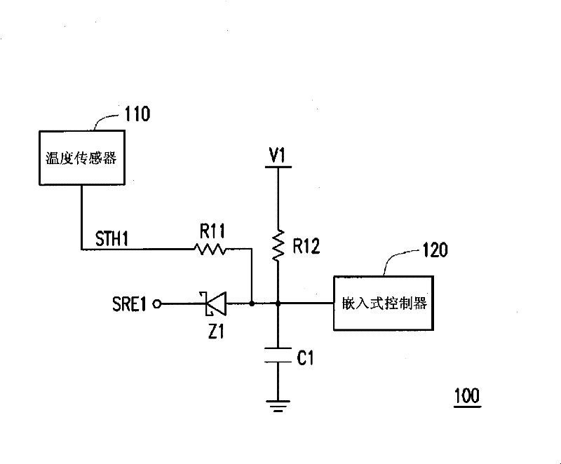
technical field [0001] The present invention relates to a computer system and its power control device, and in particular to a computer system with an over-temperature protection mechanism and its power control device. Background technique [0002] figure 1 A partial schematic diagram of a traditional computer system. refer to figure 1 , the conventional computer system 100 includes a temperature sensor 110, an embedded controller 120, resistors R11 and R12, a capacitor C1, and a diode Z1. Under normal conditions of the conventional computer system 100 , the temperature sensor 110 will not generate the sensing signal STH1 with a low logic level. At this time, the voltage V1 will pass through the conduction path of the resistor R12 and the capacitor C1, so that the embedded controller 120 works normally. [0003] Conversely, when the traditional computer system 100 is overheated due to the CPU or a certain working element, the temperature sensor 110 will generate a sensin...

Claims


Application Information

Patent Timeline
Patent Type & Authority Patents(China)
IPC IPC(8): G06F1/26
Inventor 吕俊颖
Owner 贵州聚控科技有限公司
Learn More