Cable drum fixing rack

A technology for fixing frames and cables, which is applied in thin material handling, conveying filamentous materials, transportation and packaging, etc. It can solve the problems of fixed frame structure, waste of resources, difficulty in meeting the universal application of cable reels, etc., to prevent Rotating loose, easy to use, convenient for on-site manual adjustment

Pending Publication Date: 2017-01-11
JIANGSU ELECTRIC POWER CO +1
View PDF0 Cites 12 Cited by
  • Summary
  • Abstract
  • Description
  • Claims
  • Application Information

AI Technical Summary

Problems solved by technology

[0003] The technical problem to be solved by the present invention is that the structure of the existing fixing frame is fixed, and it is difficult to meet the universal application of cable reels of various models and sizes, resulting in a lot of waste of resources

Method used


Image

  • Cable drum fixing rack
  • Cable drum fixing rack

Examples


Embodiment Construction

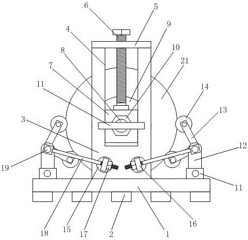
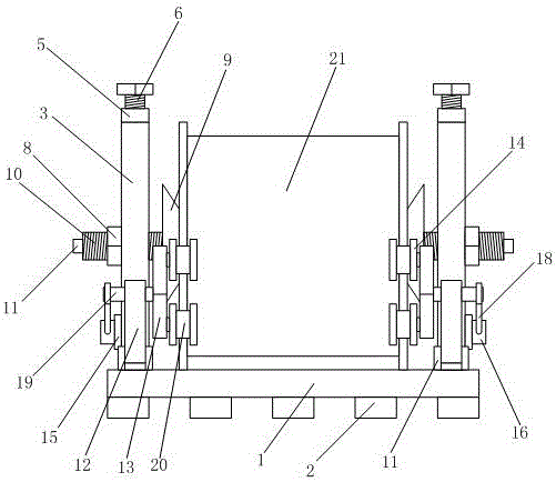
[0012] Such as figure 1 and 2 As shown, the cable reel fixing frame of the present invention includes: a base plate 1 , a support block 2 and two clamping mechanisms arranged symmetrically on the left and right sides of the base plate 1 .

[0013] Among them, the support blocks 2 are installed in an array on the lower side of the bottom plate 1; the clamping mechanism includes side plates 3, beams 5, lifting screws 6, sliders 7, extrusion screws 8, lock nuts 10, and conical extrusion heads 9 And rotating handle bar 11; Side plate 3 is vertically installed on the upper side of base plate 1; On side plate 3, be provided with a chute 4 vertically; Beam 5 is horizontally arranged at the upper end notch place of chute 4; Slider 7 Embedded in the chute 4, and can lift and slide along the chute 4; the lifting screw 6 is vertically screwed on the beam 5, and the lower end of the lifting screw 6 is rotatably installed on the slider 7; the extrusion screw 8 is threaded and screwed On ...


PUM


Abstract

The invention provides a cable drum fixing rack. The cable drum fixing rack comprises a bottom plate, supporting blocks and two clamping mechanisms. The supporting blocks are installed on the lower side of the bottom plate in an array mode. Each clamping mechanism comprises a side plate, a cross beam, a lifting screw, a sliding block, an extrusion screw, a locking nut, a conical extrusion head and a rotating handle lever. The side plates are vertically installed on the upper side of the bottom plate. A sliding chute is vertically formed in each side plate. Each cross beam is horizontally arranged at the position of an upper end notch of each sliding chute. Each sliding block is embedded into the corresponding sliding chute. Each lifting screw is screwed onto the corresponding cross beam, and the lower end of each lifting screw is installed on the corresponding sliding block in a rotating mode. Each extrusion screw is screwed onto the corresponding sliding block in a threaded mode. Each conical extrusion head is installed at the end, stretching into the gap between the two side plates, of the corresponding extrusion screw, and each rotating handle lever is installed at the other end of the corresponding extrusion screw. Each locking nut is screwed onto the corresponding extrusion screw. The two side plates of the two clamping mechanisms are parallel to each other. The fixing rack is suitable for cable drums of different models and sizes, good universality is achieved, and using is convenient and fast.

Description

technical field [0001] The invention relates to an electric power construction device, in particular to a cable reel fixing frame. Background technique [0002] Most of the existing cable fixing frames adopt the method of dead stop positioning on both sides, that is to say, according to the different cable sizes existing in the market, the cable fixing frames of different specifications are respectively designed, and the cables are placed in the cable fixing frame according to the size during storage. inside the shelf. However, this storage method requires a large number of reserved cable fixing racks, and there is no commonality between the fixing racks of various sizes and models. Due to the changes in the size and quantity of the fixing racks that need to be stored each time, it is easy to cause some cables. There is no fixed frame for the cable, and some fixed frames are idle, which not only takes up space, but also causes a lot of waste of resources, and the utilizatio...

Claims


Application Information

Patent Timeline
Patent Type & Authority Applications(China)
IPC IPC(8): B65H49/38
CPCB65H49/38B65H2701/34
Inventor 周旸徐长海梁艳梁峻曹雯孙昕孙洪俊陈婷婷沈祝园王弢王玉鹏
Owner JIANGSU ELECTRIC POWER CO
Why Eureka
Try Eureka