Quick supporting prying device

A fast, plate-screwed technology, used in lifting devices, crowbars, etc., can solve the problems of moving and adjusting overweight objects, labor and time-consuming, etc., to achieve the effect of convenient and labor-saving operation, simple and clear structure and principle

Inactive Publication Date: 2017-01-11
张伟
View PDF0 Cites 3 Cited by
  • Summary
  • Abstract
  • Description
  • Claims
  • Application Information

AI Technical Summary

Problems solved by technology

[0002] When raising many tall objects and objects at the object support, it is often laborious and time-consuming because there is no place to start, and there is no way to move and adjust the overweight objects.

Method used


Image

  • Quick supporting prying device
  • Quick supporting prying device

Examples


Embodiment Construction

[0011] The present invention will be further illustrated below in conjunction with the accompanying drawings and specific embodiments. This embodiment is implemented on the premise of the technical solution of the present invention. It should be understood that these embodiments are only used to illustrate the present invention and are not intended to limit the scope of the present invention.

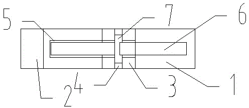
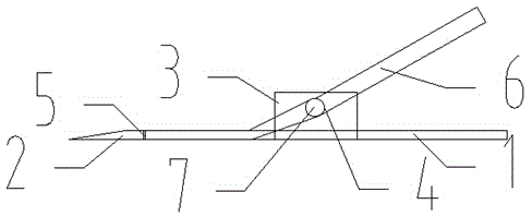
[0012] Such as Figure 1 to Figure 2 As shown, a quick support prying device includes a support plate 1, a cone tip plate 2, a rotating splint 3, a rotating hole 4, a square groove 5, a bending prying plate 6, and a rotating cylinder 7.

[0013] The side end face of the cone tip plate 2 is fixedly connected with the front end face of the support board 1, and the center fits, and the lower end of the rotating splint 3 is fixedly connected to the middle position of the upper end face of the support board 1, and the left and right symmetrical board faces are opposite.

[0014] The rotating...


PUM


Abstract

The invention discloses a quick supporting prying device. The quick supporting prying device comprises a supporting insertion plate, a conical tip plate, a rotary clamping plate, a rotary hole, a square slot, a bending prying plate and a rotary cylinder. The device disclosed by the invention is simple and clear in structure principle. By means of using a combined metal thin plate sheet, the device enters a crack through a back impact force, and one end of the device is pried by treading or heavily pressing to lift an object up, so that the whole operation is convenient and labor-saving and safe and effective.

Description

technical field [0001] The invention relates to a supporting device, in particular to a fast supporting prying device. Background technique [0002] For a lot of high objects and objects at the object supporting place, when it is raised, it is often laborious and time-consuming because there is no place to start, and there is no way to move and adjust the overweight objects. Contents of the invention [0003] The object of the present invention is to provide a quick support prying device for the deficiencies in the prior art. [0004] In order to achieve the above-mentioned purpose, the method adopted in the present invention is: a quick support prying device, including a support plate, a cone tip plate, a rotating splint, a rotating hole, a square groove, a bending prying plate, and a rotating cylinder; The side end face of the tapered tip plate is fixedly connected with the front end face of the supporting board, and the center fits. The lower end of the rotating splint...

Claims


Application Information

Patent Timeline
Patent Type & Authority Applications(China)
IPC IPC(8): B66F15/00
Inventor 张伟
Owner 张伟
Why Eureka
Try Eureka