Push-pull lock

A technology of push-pull locks and push-pull mechanisms, applied in the field of push-pull locks, can solve the problems of poor versatility of push-pull mechanisms, and achieve the effect of good versatility and convenient use

Active Publication Date: 2017-01-11
深圳市凯迪仕智能科技股份有限公司
View PDF5 Cites 11 Cited by
  • Summary
  • Abstract
  • Description
  • Claims
  • Application Information

AI Technical Summary

Problems solved by technology

[0003] Based on this, it is necessary to provide a push-pull lock for

Method used


Image

  • Push-pull lock
  • Push-pull lock
  • Push-pull lock

Examples


Embodiment Construction

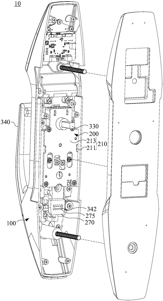
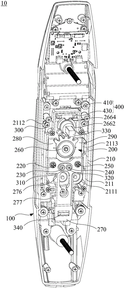
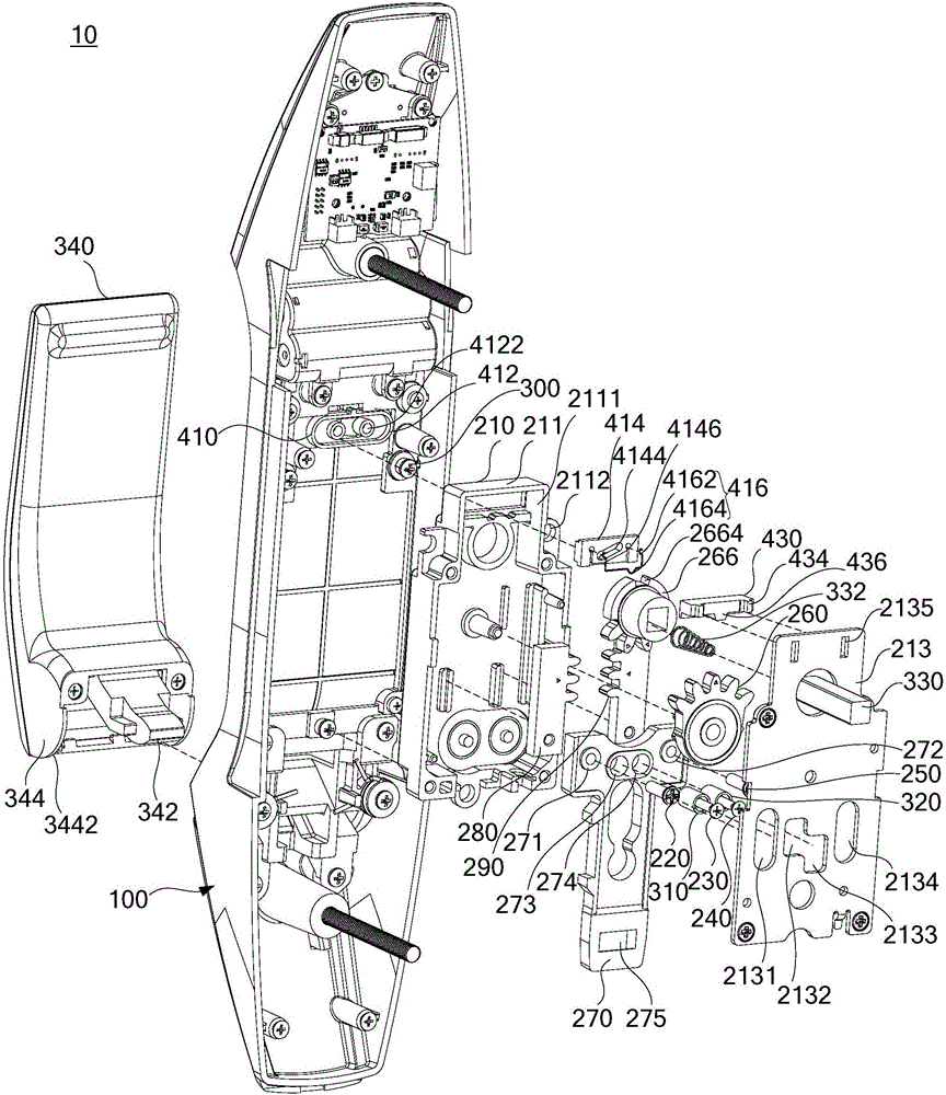
[0033] In order to facilitate the understanding of the present invention, the push-pull lock will be described more fully below with reference to the relevant drawings. A preferred embodiment of the push-pull lock is given in the accompanying drawings. However, the push-pull lock can be implemented in many different forms and is not limited to the embodiments described herein. On the contrary, the purpose of providing these embodiments is to make the disclosure of the push-pull lock more thorough and comprehensive.

[0034] It should be noted that when an element is referred to as being “fixed” to another element, it can be directly on the other element or there can also be an intervening element. When an element is referred to as being "connected to" another element, it can be directly connected to the other element or intervening elements may also be present. The terms "vertical," "horizontal," "left," "right," and similar expressions are used herein for purposes of illust...


PUM


Abstract

The invention relates to a push-pull lock. The above push-pull lock comprises a lock body and a push-pull mechanism arranged on the lock body. The push-pull mechanism comprises a shell, a first connecting piece, a second connecting piece, a third connecting piece, a fourth connecting piece, a gear assembly, a movable rod, a first rack and a second rack. The shell comprises a first shell body and a second shell body covering the first shell body. The first shell body is provided with a containing cavity, and the second shell body is provided with a first limiting hole, a second limiting hole, a third limiting hole and a fourth limiting hole, all of which communicate with the containing cavity. The shell is used for being fixed to the lock body. At least part of the first connecting piece is located in the first limiting hole, and the first connecting piece can slide in the first limiting hole. According to the above push-pull lock, the universality of the push-pull mechanism is high, and accordingly the push-pull lock can be conveniently used by users.

Description

technical field [0001] The invention relates to the technical field of door locks, in particular to a push-pull lock. Background technique [0002] The push-pull mechanism of the push-pull lock is used to transmit the user's power to the locking mechanism to realize the unlocking action of the push-pull lock. The push-pull mechanism of a general push-pull lock can only satisfy one of the unlocking methods of "left push" or "left pull" or "right push" or "right pull". Therefore, it is necessary to know the positional relationship between the door and the door frame before installation. And according to the preset way of opening the door, to select the corresponding push-pull lock; however, in the actual operation process, due to human misjudgment, the push-pull lock cannot meet the predetermined requirements, and it needs to be replaced many times before it will be suitable. The push-pull lock is installed on the door and window. Therefore, the push-pull mechanism of the ab...

Claims


Application Information

Patent Timeline
IPC IPC(8): E05B15/00E05B3/00E05B17/20
CPCE05B3/00E05B15/00E05B17/2084
Inventor 蒋念根
Owner 深圳市凯迪仕智能科技股份有限公司
Why Eureka
Try Eureka