Novel magnetic door stopper hinge

A magnetic door and suction hinge technology, which is applied in door/window accessories, wing leaf fastening devices, building fastening devices, etc., can solve the problems of inconvenient use environment or installation environment, harm to human body, damage to door stoppers, etc. Achieve the effects of good practical performance, reliable connection, and reduced use cost

Inactive Publication Date: 2017-01-11
PINGHU FUDA HARDWARE MFG CO LTD
View PDF5 Cites 7 Cited by
  • Summary
  • Abstract
  • Description
  • Claims
  • Application Information

AI Technical Summary

Problems solved by technology

[0003] When the existing door is installed, the door and the door frame need to be fixedly connected through the door hinge. The current door hinge includes left and right hinges, and the left and right hinges are provided with through holes. After the assembly is completed, the opening of the door is fixed by setting a door stopper on the wall. Although it can play a fixed role, the door stopper has an extended end, which is easy to break due to the heavy closing of the door, and it is easy for people to accidentally close the door Touching the door stopper will not only harm the human body but also damage the door stopper
[0004] In the existing magnetic door suction hinge, the twisted shaft sleeve on the fixed hinge is located in the middle of the fixed plate of the door frame. The angle on the steel sleeve can change the suction angle between the door hinge and the fixed hinge, so that the suction angle can be adjusted according to different use environments or installation environments. The cover will touch the door line during the rotation, which will limit the opening angle between the door hinge and the fixed hinge, which will bring inconvenience to the use environment or installation environment of the door.

Method used


Image

  • Novel magnetic door stopper hinge
  • Novel magnetic door stopper hinge
  • Novel magnetic door stopper hinge

Examples


Embodiment

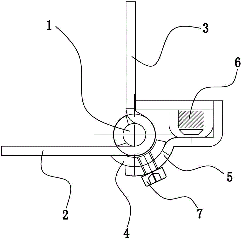
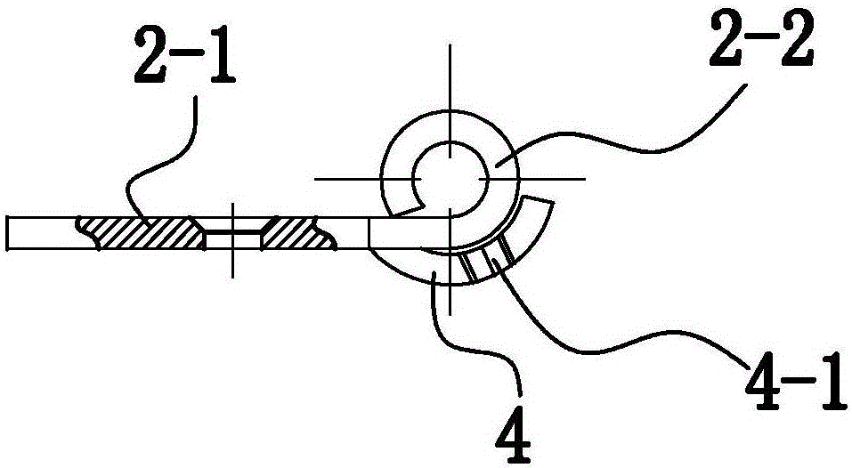
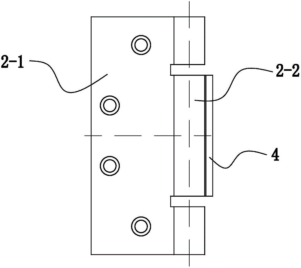
[0028] Example: such as Figure 1-7 As shown, a novel magnet door suction hinge includes a hinge shaft 1, a fixed hinge leaf 2 and a door hinge leaf 3 respectively rotatably connected to the hinge shaft 1, and a steel sleeve 4 and a steel sleeve 4 are also provided outside the hinge shaft 1. One end is fixedly connected to the fixed hinge 2, and the steel sleeve 4 is rotatably connected with an adjustment sleeve device 5 for adjusting the suction angle between the door hinge 3 and the fixed hinge 2. The adjustment sleeve device 5 and the door hinge 3 form a An included angle not less than 90°, the adjustment sleeve device 5 is provided with a magnet 6, and correspondingly, the door hinge 3 is provided with a suction plate 3-1 that is attracted to the magnet 6, and the suction plate 3-1 It forms an included angle of 90° with the door hinge 3, and the suction plate 3-1 is integrally formed with the door hinge 3; the above-mentioned structure increases the overall strength of the...


PUM


Abstract

The invention relates to a novel magnetic door stopper hinge. The novel magnetic door stopper hinge comprises a hinged shaft, a fixed hinge and a door hinge, wherein the fixed hinge and the door hinge are respectively rotationally connected to the hinged shaft; a steel sleeve is also arranged outside the hinged shaft; one end of the steel sleeve is fixedly connected to the fixed hinge; the steel sleeve is rotationally connected with an adjusting sleeve device for adjusting the suck-engagement angle between the door hinge and the fixed hinge; a magnet is arranged on the adjusting sleeve device; a suck-engagement plate which can have suck-engagement with the magnet is arranged on the door hinge; the fixed hinge comprises a door frame fixing plate and a first twist shaft sleeve; the end part of the door frame fixing plate is tangent to the first twist shaft sleeve; the door hinge comprises a door fixing plate and a second twist shaft sleeve. The novel magnetic door stopper hinge disclosed by the invention is simple and reasonable in structure; by rotating the angle of the adjusting sleeve on the fixed hinge to change the suck-engagement angle between the door hinge and the fixed hinge, the suck-engagement angle can be adjusted according to different use environments or installation environments; the novel magnetic door stopper hinge is convenient in adjustment, reliable in connection, lowered in use cost and convenient to operate.

Description

technical field [0001] The invention relates to the field of mechanical technology, in particular to a novel magnetic door suction hinge. Background technique [0002] The door stopper is also commonly known as the door touch, and it is also a device that absorbs and positions the door leaf after it is opened, so as to prevent the wind from blowing or touching the door leaf and closing it. Door stoppers are divided into two types: permanent magnet stoppers and electromagnetic door stoppers. Permanent magnet stoppers are generally used in ordinary doors and can only be controlled manually; electromagnetic door stoppers are used in electrically controlled door and window equipment such as fire doors, which have both manual control and automatic control. control function. [0003] When the existing door is installed, the door and the door frame need to be fixedly connected through the door hinge. The current door hinge includes left and right hinges, and the left and right hin...

Claims


Application Information

Patent Timeline
Patent Type & Authority Applications(China)
IPC IPC(8): E05D5/04E05D5/14E05D7/04E05C17/56
CPCE05D5/04E05C17/56E05D5/14E05D7/0423
Inventor 徐国强
Owner PINGHU FUDA HARDWARE MFG CO LTD
Why Eureka
Try Eureka