A Method of Well Seismic Calibration Based on Time-Frequency Continuous Wavelet Transform

A technology of wavelet transform and well seismic calibration, which is applied in the field of oil and gas geophysical exploration, can solve the problems of greater influence of familiarity, low accuracy and reliability of calibration results, difficulty in achieving accurate calibration of horizons, etc., and achieve accurate calibration results

Active Publication Date: 2018-09-04
CHINA PETROLEUM & CHEM CORP +1
View PDF6 Cites 0 Cited by
  • Summary
  • Abstract
  • Description
  • Claims
  • Application Information

AI Technical Summary

Problems solved by technology

However, for the precise calibration of target horizons in lithologic oil and gas reservoirs, it is difficult to accurately calibrate horizons due to factors such as drift in logging and complex formations.
Although well-seismic calibration with multi-information fusion, drilling and geological joint calibration, well-seismic frequency division calibration and other methods have been developed, and some successful application examples have been obtained, the successful application of these methods is restricted by many factors, especially for general The familiarity of engineering and technical personnel with geology, logging and seismic data in the work area and the experience of the technical personnel have a great influence, and the accuracy and reliability of the calibration results are not high

Method used


Image

  • A Method of Well Seismic Calibration Based on Time-Frequency Continuous Wavelet Transform
  • A Method of Well Seismic Calibration Based on Time-Frequency Continuous Wavelet Transform
  • A Method of Well Seismic Calibration Based on Time-Frequency Continuous Wavelet Transform

Examples


Embodiment 1

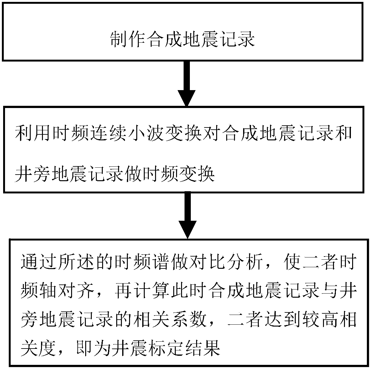
[0065] The time-frequency continuous wavelet transform well seismic calibration method in this embodiment is to finely calibrate the well seismic of a certain well in Chunguang Oilfield, and its implementation process is as follows figure 1 shown, including the following specific steps:

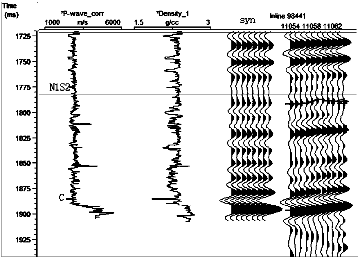
[0066] 1) Using the acoustic logging velocity and density logging data of a well in Chunguang Oilfield to make synthetic seismic records, and compare and analyze them with the seismic records near the well, and carry out preliminary well seismic calibration. The results are as follows: figure 2 shown.

[0067] figure 2Among them, P-wave_corr is the acoustic logging velocity curve; Density is the density logging curve; syn is the synthetic seismic record; Inline98441 is the position of the seismic trace where the well is located, and 5 seismic traces are displayed on the left and right of the center, and N1S2 is Shawan C is the seismic interpretation horizon of the bottom interface of the ...


PUM


Abstract

The invention discloses a time-frequency continuous wavelet transform well-to-seismic calibration method comprising the following steps that 1) a synthetic seismic record is made by using logging data; 2) time-frequency transform is performed on the synthetic seismic record and a well-side seismic record by using a time-frequency continuous wavelet transform method so that the time-frequency distribution diagram of the synthetic seismic record and the well-side seismic record is obtained; 3) the time-frequency axes of the synthetic seismic record and the well-side seismic record are enabled to be aligned by adjusting the time-frequency distribution diagram, the synthetic seismic record and / or the well-side seismic record are synchronously adjusted and then well-to-seismic calibration is performed; 4) the correlation analysis coefficient of the synthetic seismic record and the well-side seismic record is calculated; if the correlation analysis coefficient is greater than or equal to 0.9, the calibration result is reliable; and if the correlation analysis coefficient is less than 0.9, the calibration result is not reliable, and the process returns to the step 1) to perform calibration again. With application of the well-to-seismic calibration method, the well and semiotic time-depth relationship can be more efficiently and accurately determined with the help of the logging and seismic data so that the calibration result is accurate and reliable.

Description

technical field [0001] The invention belongs to the technical field of oil and gas geophysical exploration, and in particular relates to a well seismic calibration method of time-frequency continuous wavelet transform. Background technique [0002] As we all know, the vertical depth of well logging data is represented by drilling depth, while the vertical depth of seismic data is represented by time. Therefore, well-seismic calibration is the link and the most important link to connect well logging and seismic data. Conventional well-seismic calibration methods mainly use acoustic wave and density logging curves of well logging data to make synthetic seismic records, and then compare and analyze them with side-hole seismic traces to perform time-depth calibration. The method is reliable for structural exploration, and for the correlation of large sets of strata. However, for the precise calibration of target horizons in lithologic reservoirs, it is difficult to achieve accu...

Claims


Application Information

Patent Timeline
Patent Type & Authority Patents(China)
IPC IPC(8): G01V1/40G01V1/30
CPCG01V1/30G01V1/40
Inventor 肖学田仁飞刘焕王鹏飞邓继新李秋菊邢丽娟黎腾
Owner CHINA PETROLEUM & CHEM CORP
Why Eureka
Try Eureka