Resistivity anisotropy recognition method in horizontal well stratum environment

A technology of anisotropy and identification method, which is applied in the field of resistivity anisotropy identification in the formation environment of horizontal wells, and can solve problems such as the inability to provide layer boundary distance and anisotropy.

Active Publication Date: 2017-01-11
HANGZHOU SUMAY TECH
View PDF5 Cites 22 Cited by
  • Summary
  • Abstract
  • Description
  • Claims
  • Application Information

AI Technical Summary

Problems solved by technology

However, the traditional combined resistivity inversion is mainly for one-dimensional and (or) two-dimensional inversion for rotationally symmetric formations, which is not s...

Method used


Image

  • Resistivity anisotropy recognition method in horizontal well stratum environment
  • Resistivity anisotropy recognition method in horizontal well stratum environment
  • Resistivity anisotropy recognition method in horizontal well stratum environment

Examples


Embodiment 1

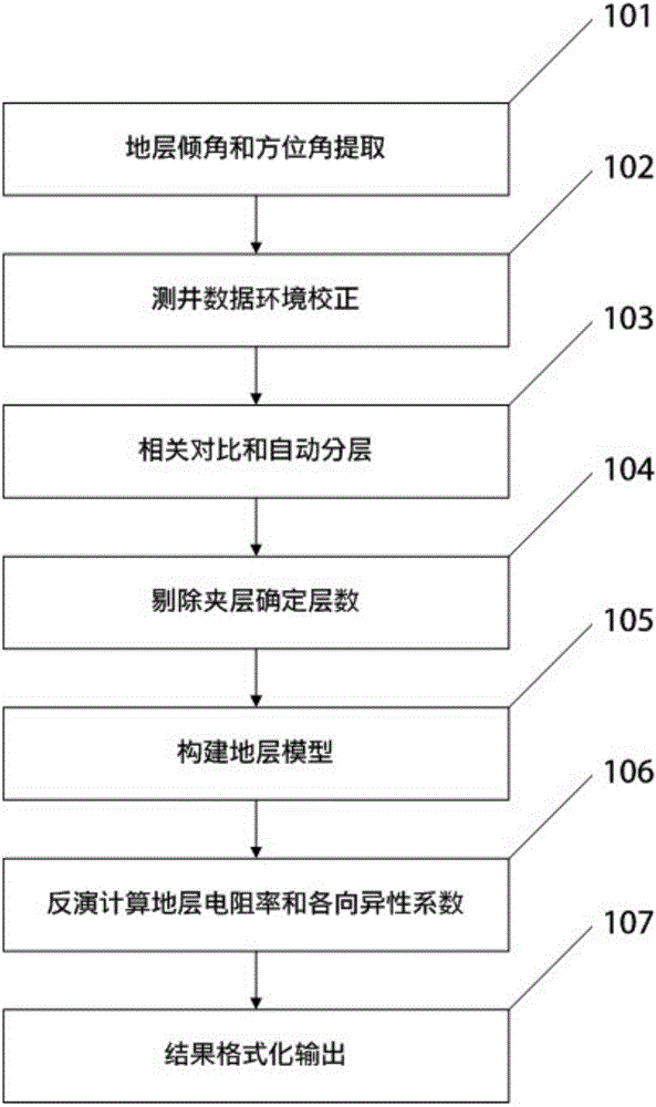
[0104] The method for identifying resistivity anisotropy in a horizontal well formation environment provided in this embodiment includes the following steps:

[0105] Step 1. Obtain the azimuth natural GR and azimuth resistivity logging response values ​​according to the horizontal well logging, and use the elevation difference and curve fitting to extract the logging instrument-the formation relative inclination angle and the formation azimuth angle;

[0106] Step 2, performing azimuth correction on the azimuth resistivity logging and azimuthal resistivity logging data according to the dip angle and azimuth angle obtained in step 1;

[0107] Step 3. For the standardized data after azimuth correction, the curve activity is obtained by the correlation comparison method, and the formation interface is divided by the activity method. When dividing the formation interface, the natural GR curve, the azimuth resistivity logging curve, and the azimuth resistivity curves, neutron dens...

Embodiment 2

[0159] This embodiment provides a method for identifying formation anisotropy using azimuthal resistivity logging in complex borehole environments such as horizontal wells and highly deviated wells; it is realized through the following steps:

[0160] Step 1 uses the elevation difference of well logging curves and nonlinear fitting method to extract formation dip and azimuth, including the following steps:

[0161] 1) Use the four azimuth natural GR curves measured by the ABG logging tool to extract the dip angle, and perform a correlation analysis on the four GR curves to obtain the elevation difference of the corresponding layer, which is the six points on the inclined layer of the formation. Since the expansion diagram of the intersection of the borehole wall and the inclined layer appears as a single-period sine function on the image, it satisfies the equation:

[0162] y=Asin(ωx-β)+y 0 (1)

[0163] 2) Non-linear fitting, solve the undetermined coefficient in equation (...

Embodiment 3

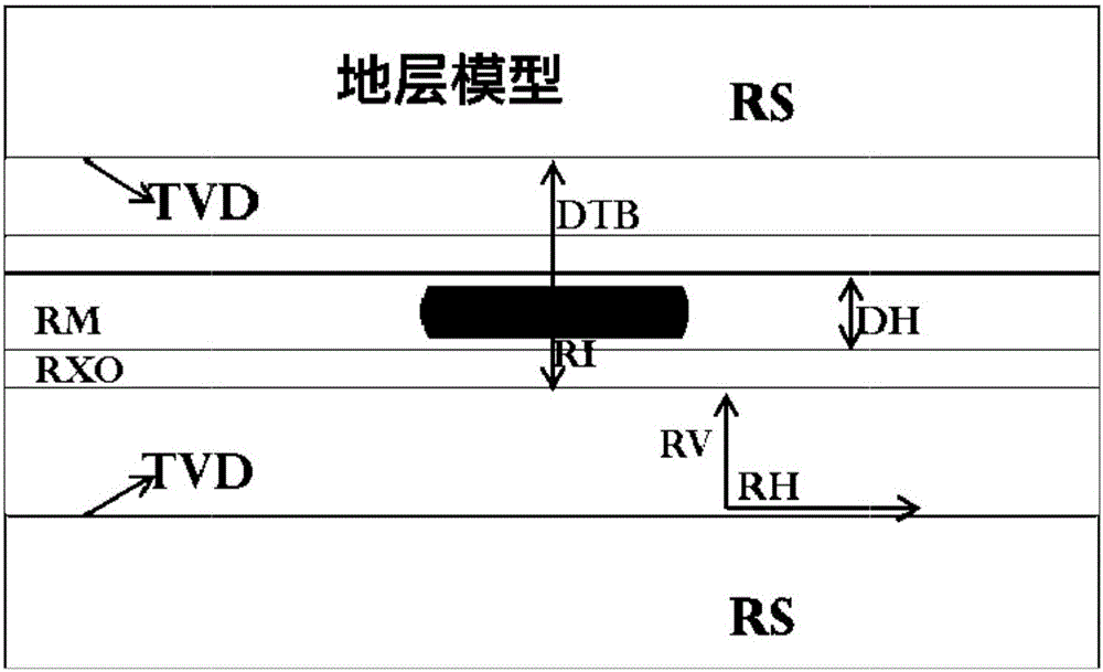
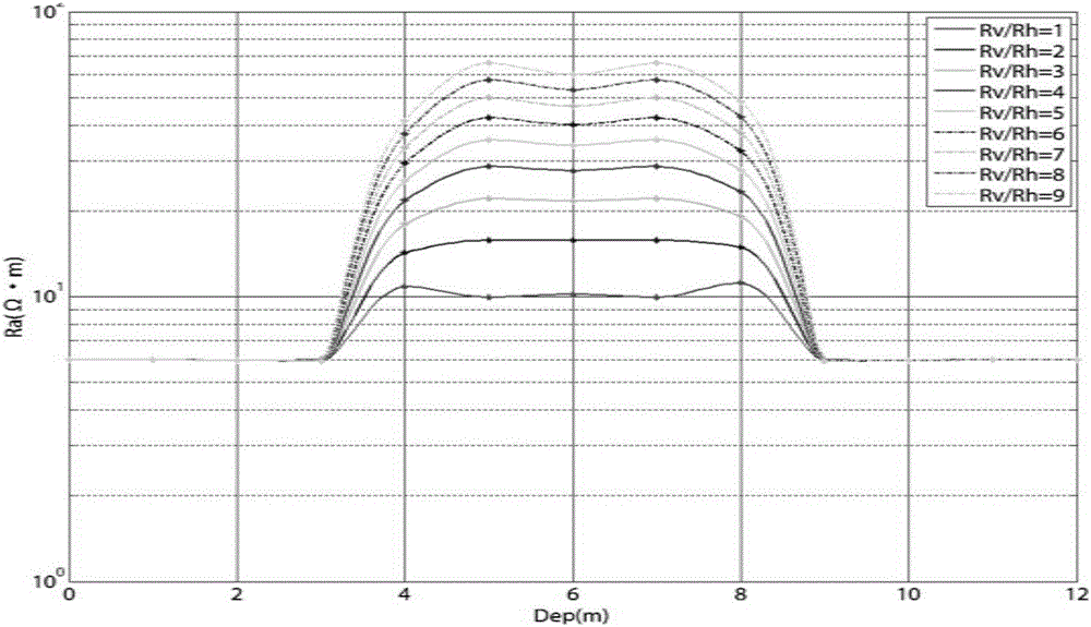
[0190] as the picture shows, figure 1 It is a flow chart of a specific embodiment of the method for identifying resistivity anisotropy in the horizontal well formation environment of the present invention; figure 2 It is a schematic diagram of horizontal well formation modeling of the present invention, in which TVD represents the layer boundary position, RM represents the mud resistivity, RI represents the invasion depth, RXO represents the invasion zone resistivity, RS represents the surrounding rock resistivity, and Rh-Rv represents the target level Resistivity - vertical resistivity, DH means borehole diameter; image 3 The horizontal downhole apparent resistivity of the present invention changes with the formation anisotropy coefficient; Figure 4 The phase difference resistivity and amplitude ratio resistivity difference of the apparent resistivity of the present invention vary with the anisotropy coefficient; Figure 5 In the anisotropic formation of the present inve...


PUM


Abstract

The invention discloses a resistivity anisotropy recognition method in a horizontal well stratum environment. Firstly, an azimuth natural GR and an azimuth resistivity logging are obtained through logging, and then a stratigraphic dip and a stratigraphic azimuth angle are extracted. Secondly, the instrument azimuthal resistivity logging response value at multiple spacings and different frequencies in a horizontal well are acquired through logging. Through the environmental correction and automatic layering process, a false layer is removed, and standardized logging data and a stratum layering interface are obtained. Thirdly, according to a stratigraphic dip extracting result, the layering interface, an apparent resistivity measured value and adjoining well data, a horizontal well stratum model is constructed. Finally, the stratum model is subjected to back calculation, and then an anisotropy coefficient and a stratum resistivity inversion result are outputted. According to the method, the real resistivity information and the anisotropy coefficient information of the stratum in the horizontal well environment are extracted based on azimuthal resistivity logging data while drilling, so that the existing logging evaluation data of the horizontal well are perfected. During the comprehensive interpretation and evaluation process of the logging data of the horizontal well, the reservoir oil saturation and the like can be accurately calculated based on the stratum real resistivity and the anisotropy coefficient. As a result, the method provides reliable parameters for reservoir evaluation.

Description

technical field [0001] The invention relates to the technical field of oilfield development, in particular to a method for identifying resistivity anisotropy in a horizontal well formation environment. Background technique [0002] With the continuous deepening of exploration and development of complex oil and gas fields, the wide application of highly deviated wells, horizontal wells and other complex process wells, research on logging-while-drilling technology and R&D of logging-while-drilling instruments have received sufficient attention and developed rapidly. The transmitting coil and receiving coil of the traditional electromagnetic logging while drilling tool are coaxial, and the measured formation signal is the average value of formation information, which does not have azimuth characteristics, and cannot accurately obtain information such as formation resistivity anisotropy. Azimuth while drilling electromagnetic wave logging tools are very different from traditiona...

Claims


Application Information

Patent Timeline
IPC IPC(8): G01V3/38
CPCG01V3/38
Inventor 张中庆
Owner HANGZHOU SUMAY TECH
Why Eureka
Try Eureka