Photoelectric lock

A photoelectric and battery technology, applied in the field of mechanical and electrical machinery, can solve problems such as weak anti-theft

Active Publication Date: 2019-08-09
徐州天骋智能科技有限公司
View PDF7 Cites 0 Cited by
  • Summary
  • Abstract
  • Description
  • Claims
  • Application Information

AI Technical Summary

Problems solved by technology

The same anti-theft is not strong

Method used


Image

  • Photoelectric lock
  • Photoelectric lock
  • Photoelectric lock

Examples


Embodiment Construction

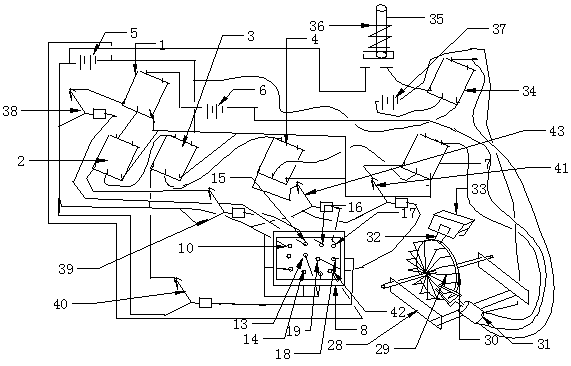
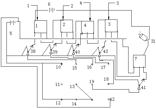
[0008] exist figure 1 Among them, on a password plate 8, there are a plurality of energized contacts and light sensors; the first energized contact 10, the 3rd energized contact, the 4th energized contact 14, the 5th energized contact 13 and the 6th energized contact Connect the positive electricity of the first battery 5 respectively; The second energized contact is empty; The negative pole of the first battery is connected on the eighth energized contact 42; The first light sensor 18 is connected to the base of the first triode 40, which The collector is connected to the circuit of the first battery, its emitter is connected to a relay pin of the first relay 3, and its other relay pin is connected to the negative pole of the first battery 5; the second light sensor 17 is connected to the second The base of a transistor 43, its collector is connected to the circuit of the first battery, its emitter is connected to a relay pin of the second relay 4, and its other relay pin is ...


PUM


Abstract

A photo-electric lock falls under the electromechanical field and solves the anti-theft performance of locks. The first optical sensor 18 is connected to the base electrode of the first triode 40, its collector is connected to the circuit of the first battery, its emitter is connected to one relay pin of the first relay 3, and the other relay pin of it is connected to the negative pole of the first battery 5; positive pole of the second battery 6 is connected to the normally open end of the first relay, the common end of the first relay is connected the normally open end of the second relay, the common end of the second relay is connected to the normally open end of the third relay, the common end of the third relay is connected to the normally end of the fourth relay, the common end of the fourth relay is connected to the common end of the fifth relay, the normally closed end of the fifth relay is connected to motor 30 before it is connected back to the negative pole of the second battery. The present invention is intended for civilian applications.

Description

technical field [0001] A photoelectric lock belongs to the mechanical and electrical field. Background technique [0002] At present, various tumbler locks and smart locks are popular in the market. The tumbler lock can be unlocked technically, and the anti-theft performance is poor. Smart locks are too simple and can be imitated, and some are interoperable with tumbler locks. The same anti-theft is not strong. Contents of the invention [0003] A kind of photoelectric lock is provided here, this kind of lock does not have password, does not need people to input password to unlock. The password is stored inside the key and inside the password board, and is opened with photoelectricity, so the anti-theft property is very strong. [0004] This invention is like this: on a password plate 8, there are a plurality of energized contacts and light sensors; The six energized contacts are respectively connected to the positive electricity of the first battery 5; the second ene...

Claims


Application Information

Patent Timeline
Patent Type & Authority Patents(China)
IPC IPC(8): E05B49/00E05B19/00E05B47/00
CPCE05B19/00E05B47/0012E05B49/006
Inventor 王光树
Owner 徐州天骋智能科技有限公司
Why Eureka
Try Eureka