

Bill position detector
A technology for detecting devices and bills, which is applied to devices for accepting coins, handling coins or valuable banknotes, and instruments. Easy and fast effect
- Summary
- Abstract
- Description
- Claims
- Application Information
AI Technical Summary
Problems solved by technology
Method used
Image

Examples
Embodiment Construction
[0025] In the following description, numerous specific details are given in order to provide a more thorough understanding of the present invention. Of course, the present invention can also have other embodiments besides these detailed descriptions.
[0026] The bill detection device of the present invention will be described in detail below in conjunction with specific embodiments and accompanying drawings.
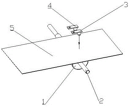
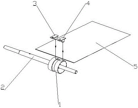
[0027] refer to figure 1 and figure 2 As shown, the bill position detection device of the present invention mainly includes the following composition structures:
[0028] light guide wheel 1;
[0029] The rotating shaft 2 is fixedly connected with the light guide wheel 1 to drive the light guide wheel 1 to rotate;
[0030] The emission sensor 3 is used to emit infrared light;
[0031] The receiving sensor 4 is arranged adjacent to the transmitting sensor 3 to receive infrared light.
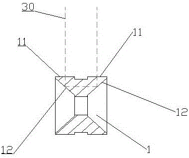
[0032] As a preferred embodiment, the light guide wheel 1 is arranged on the di...
PUM
 Abstract
Description
Claims
Application Information