an isolating switch

A technology of isolating switches and moving contacts, which is applied to electric switches, air switch components, high-voltage air circuit breakers, etc., and can solve problems such as reduced reliability, long arc residence time, and high production costs

Active Publication Date: 2019-04-02
温州奥来电器有限公司
View PDF5 Cites 0 Cited by
  • Summary
  • Abstract
  • Description
  • Claims
  • Application Information

AI Technical Summary

Problems solved by technology

[0002] The existing isolating switch structure is a multi-contact isolating switch. A plurality of moving contacts move up and down linearly under the direct drive of the handle and the connecting rod to realize the separation and contact of the dynamic and the static, thereby realizing the closing and opening of the isolating switch. The product has some shortcomings: 1. The use of precious metals is large, the production cost is high, and the reliability is also reduced due to the large number of contacts; 2. There is no quick closing device, and the closing speed of the product depends on the speed of the human-operated handle. It is beneficial to the electrical life of the product; 3. There is no arc strike pin, the arc stays between the dynamic and static contacts for a long time, and the contacts of the product are easily burned during the opening and closing operations; 4. The product does not have an indicating device to indicate the contact of the product. The position of the head or the opening and closing state will bring a lot of inconvenience to the user

Method used


Image

  • an isolating switch
  • an isolating switch
  • an isolating switch

Examples


Embodiment Construction

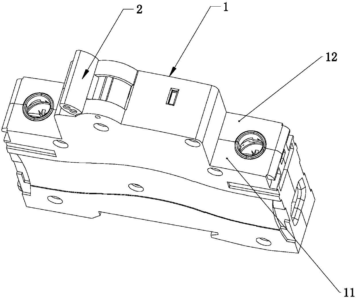
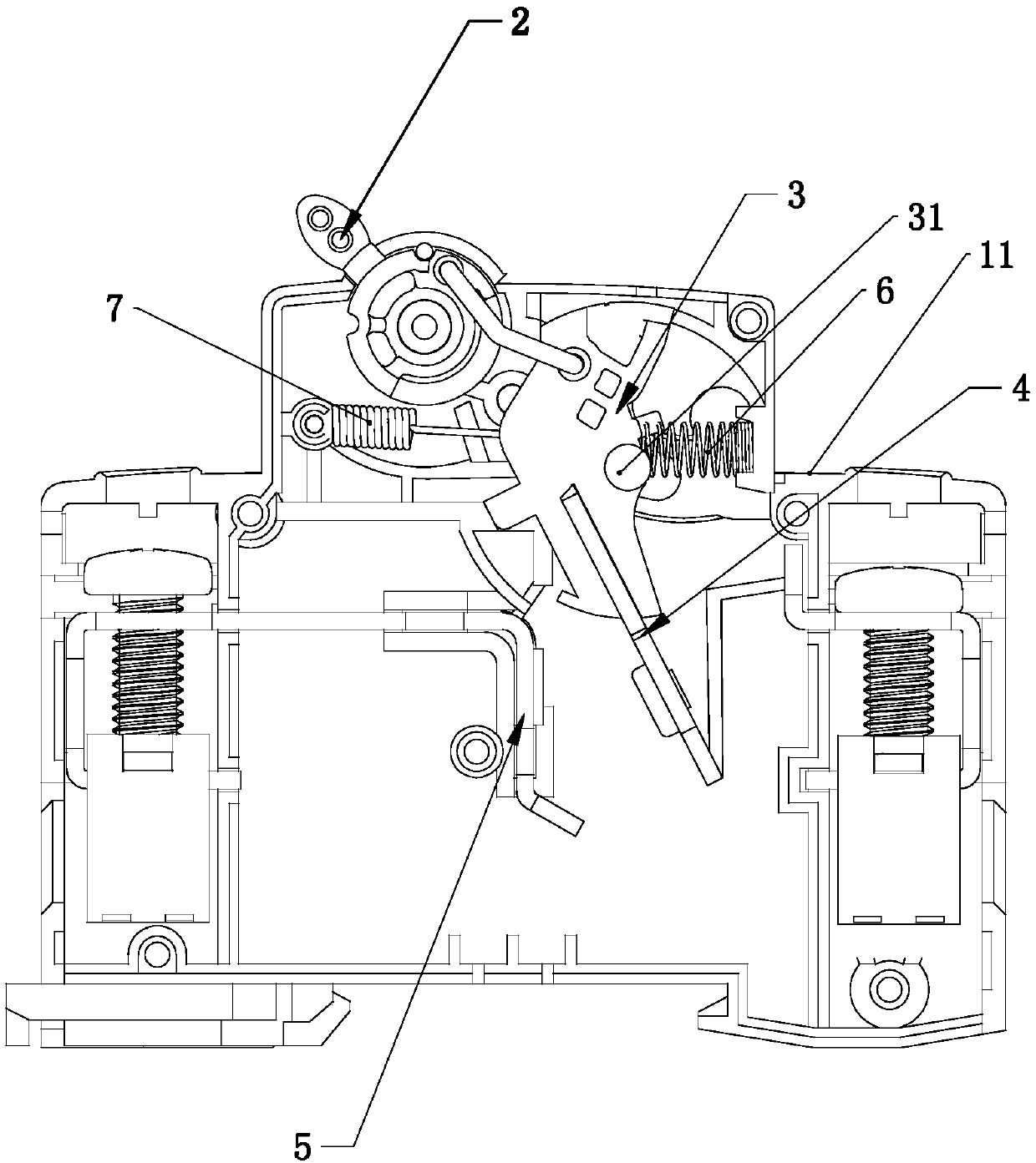
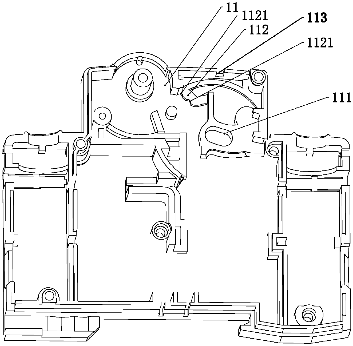
[0030] Such as figure 1 — Figure 15 As shown, an isolating switch includes a housing 1, a handle 2, a moving contact bracket 3, a moving contact 4 and a static contact 5, wherein the housing 1 is divided into a base 11 and an upper housing 12, and the moving The contact 4 is fixedly arranged on the movable contact bracket 3, and the movable contact bracket 3 is movably connected with the handle 2 through a connecting rod. Elliptical accommodating grooves 111, 121, protruding columns 31 are respectively arranged on both sides of the moving contact bracket 3, and the moving contact bracket 3 is movably arranged in the oval accommodating grooves 111, 121 through the convex columns 31, the moving contact bracket 3 is movably arranged in the oval accommodating grooves 111, 121. Between the contact bracket 3 and the base 11, a spring 6 or / and a tension spring 7 are arranged, one end of the spring 6 or / and tension spring 7 acts on the base 11, and the other end acts on the moving c...


PUM


Abstract

A disconnect switch. Oval receiving grooves (111, 121) are respectively provided at corresponding positions of a base (11) and an upper housing (12) of the disconnect switch. A protruding column (31) is separately provided on both sides of a movable contact carrier (3). The movable contact carrier (3) is movably disposed in the oval receiving grooves (111, 121) by means of the protruding columns (31). A spring (6) or / and a tension spring (7) is provided between the movable contact carrier (3) and the base (11). One end of the spring (6) or / and one end of the tension spring (7) acts on the base (11) and the other end acts on the movable contact carrier (3). The point of action of the spring (6) or / and the tension spring (7) on the movable contact carrier (3) is located above the protruding column (31) and near the protruding column (31). The disconnect switch overcomes the shortcomings in the prior art, and provides a novel disconnect switch which is easy to operate and high in closing and opening speed and has an indication function.

Description

technical field [0001] The invention relates to a switch, in particular to an isolating switch. Background technique [0002] The existing isolating switch structure is a multi-contact isolating switch. A plurality of moving contacts move up and down linearly under the direct drive of the handle and the connecting rod to realize the separation and contact of the dynamic and the static, thereby realizing the closing and opening of the isolating switch. The product has some shortcomings: 1. The use of precious metals is large, the production cost is high, and the reliability is also reduced due to the large number of contacts; 2. There is no quick closing device, and the closing speed of the product depends on the speed of the human-operated handle. It is beneficial to the electrical life of the product; 3. There is no arc strike pin, the arc stays between the dynamic and static contacts for a long time, and the contacts of the product are easily burned during the opening and ...

Claims


Application Information

Patent Timeline
Patent Type & Authority Patents(China)
IPC IPC(8): H01H31/02
CPCH01H31/023H01H31/026
Inventor 王亮华
Owner 温州奥来电器有限公司
Why Eureka
Try Eureka