
Electric power line introduction device and non -contact insulation set appliances

A technology of introducing devices and power lines, applied in the direction of collectors, circuit devices, power collectors, etc., can solve problems such as unstable power supply and output voltage amplification

Active Publication Date: 2019-04-16
PANASONIC INTELLECTUAL PROPERTY MANAGEMENT CO LTD
View PDF3 Cites 0 Cited by
  • Summary
  • Abstract
  • Description
  • Claims
  • Application Information

AI Technical Summary

Problems solved by technology

As a result, when the pickup coil passes the above overlapping portion, the output voltage is amplified, and the power supply to the mobile device side may become unstable

Method used


Image

  • Electric power line introduction device and non -contact insulation set appliances
  • Electric power line introduction device and non -contact insulation set appliances
  • Electric power line introduction device and non -contact insulation set appliances

Examples


Embodiment Construction

[0021] The present embodiment relates to a power line intake device that draws electric power to a power supply line that supplies power to a mobile device in a non-contact manner, and a non-contact insulating collector including the same.

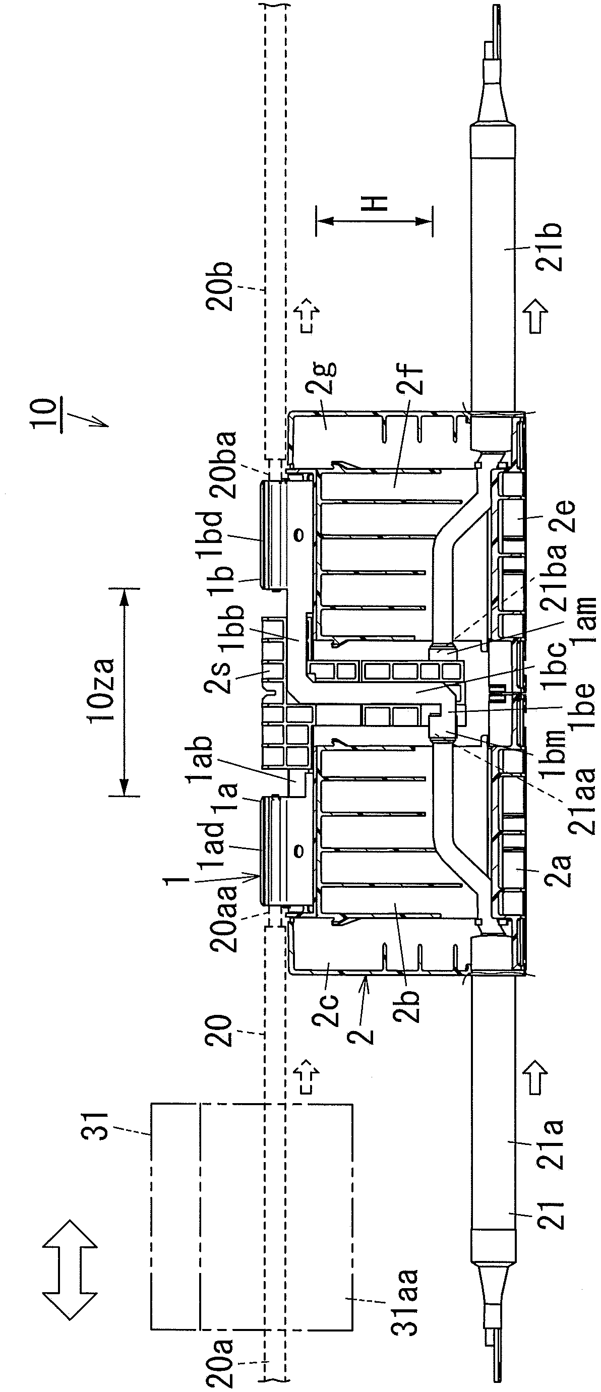
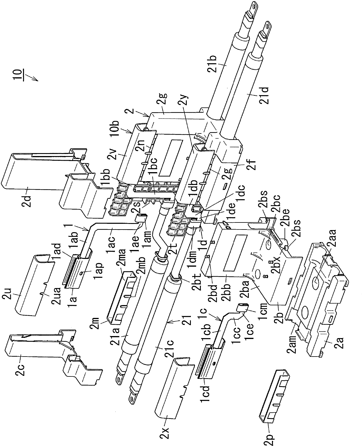
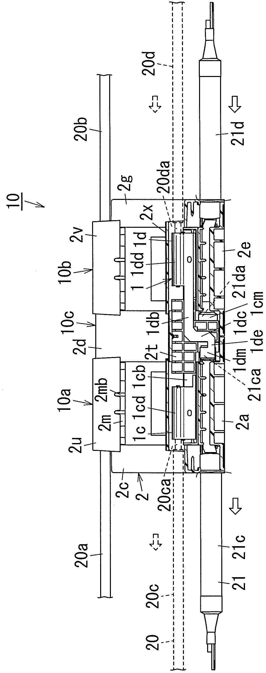
[0022] Hereinafter, for the power line inlet device 10 of the present embodiment, refer to Figure 1 to Figure 8 to illustrate. figure 1 express Figure 4 The profile in the AA direction, image 3 express Figure 4 Section in the direction of BB. Figure 9 to Figure 12 In , the non-contact insulating current collector 50 provided with the power line lead-in device 10 will be described. In the drawings, the same symbols are assigned to the same components, and overlapping descriptions are omitted. The sizes and positional relationships of components shown in the drawings are sometimes exaggerated for clarity. In the following description, each element constituting the present embodiment may be implemented in such a way that a single m...


PUM


Abstract

An object of the present invention is to provide a power line inlet device (10) capable of feeding more stable electric power, and a non-contact insulating collector (50) provided therewith. The power line lead-in device (10) of the present invention has a first connection terminal (1a) and a second connection terminal ( 1b). The first connection terminal (1a) has a first lead-out portion (1ab) leading from the first power supply line (20a) to the second power supply line (20b), and a first extension portion (1ab) intersecting the first lead-out portion (1ab). 1ac). The second connection terminal (1b) has a second lead-out portion (1bb) leading from the second power supply line (20b) to the first power supply line (20a), and a second extension portion (1bb) intersecting the second lead-out portion (1bb). 1bc). The installation member (2) overlaps the first extension part (1ac) and the second extension part (1bc) in plan view, and arranges the first lead-out part (1ab) and the second lead-out part (1bb) to face each other.

Description

technical field [0001] The present invention relates to a power line lead-in device and a non-contact insulating collector equipped with the same. Background technique [0002] Conventionally, there is a power line lead-in device that suppresses a drop in output voltage from a pickup coil when a pickup coil (pickup coil) that is a power receiving coil passes through a connecting portion (for example, refer to Document 1 [Japanese Laid-Open Patent Publication No. 2012-20656 〕). [0003] The power line inlet device of Document 1 is provided so that a protrusion for fixing the lead-in protrudes from a connecting sheet metal that holds the power supply line, and the pair of protrusions are arranged to overlap each other. The power line lead-in device of Document 1 suppresses a drop in the output voltage from the pickup coil by eliminating the portion separated between adjacent connecting sheet metals by arranging the paired protrusions to overlap each other. [0004] In additi...

Claims


Application Information

Patent Timeline
Patent Type & Authority Patents(China)
IPC IPC(8): H02J50/00
CPCB60L5/00B60M7/00H01R4/58H02J50/10
Inventor 田畑瑛树二畠康矢野绅一郎仁藤智也
Owner PANASONIC INTELLECTUAL PROPERTY MANAGEMENT CO LTD
Learn More