Multi-unit synchronous lifting machine

A lifter and group synchronization technology, applied in the direction of lifting frame, lifting device, etc., can solve the problems of small handling capacity and inconvenient use at one time, and achieve the effect of improving handling efficiency, high degree of automation, and convenient use of control

Inactive Publication Date: 2017-02-01
WUHU HENGHAO MACHINERY MFG
View PDF6 Cites 3 Cited by
  • Summary
  • Abstract
  • Description
  • Claims
  • Application Information

AI Technical Summary

Problems solved by technology

[0003] Aiming at the shortcomings of the traditional elevators, which have a small amount of handling at one time and inconvenient use, the present invention proposes a multi-group synchronous elevator

Method used


Image

  • Multi-unit synchronous lifting machine
  • Multi-unit synchronous lifting machine
  • Multi-unit synchronous lifting machine

Examples


Embodiment Construction

[0014] In order to make the technical means, creative features, goals and effects achieved by the present invention easy to understand, the present invention will be further elaborated below.

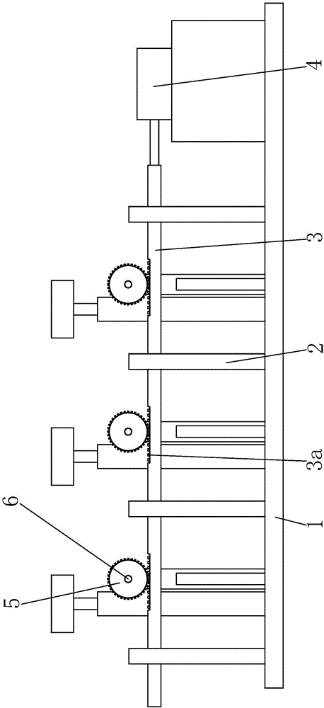
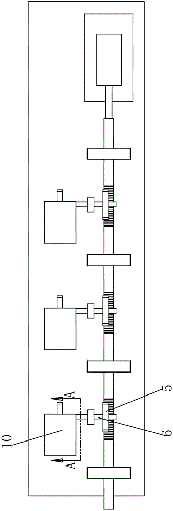
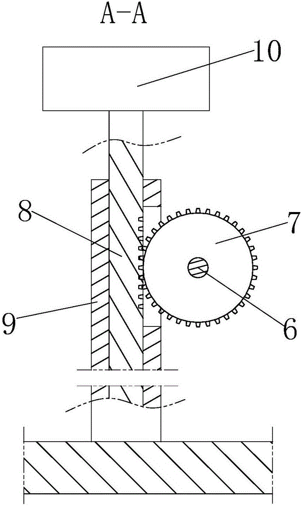
[0015] like Figure 1 to Figure 3 As shown, a multi-group synchronous elevator includes a base plate 1, and support frames 2 are arranged on the base plate 1 along the horizontal direction, and sliding rods 3 are installed on the support frame 2 through bushings. The sliding rods 3 The right end is connected with a cylinder 4, and the upper end of the sliding rod 3 is evenly distributed with a front rack 3a, and the front rack 3a is meshed with a front gear 5, and the front gear 5 is connected with a transmission shaft 6, and the transmission shaft 6 is connected with a rear gear 7, the rear part of the rear gear 7 is meshed with a rear rack 8, and the rear part of the bottom plate 1 is provided with a guide sleeve 9 for installing the corresponding rear racks 8 in a vertical sliding ma...


PUM


Abstract

The invention relates to a multi-unit synchronous lifting machine. The multi-unit synchronous lifting machine comprises a bottom plate. Bearing supports are distributed and installed on the bottom plate in the horizontal direction. A sliding rod is installed on the bearing supports through linings. The right end of the sliding rod is connected with an air cylinder. Front racks are evenly distributed at the front end of the sliding rod and engaged with front gears. The front gears are connected with transmission shafts correspondingly. The transmission shafts are connected with rear gears correspondingly. The rear portions of the rear gears are engaged with rear racks correspondingly. Guide sleeves used for installing the corresponding rear racks in a vertical sliding mode are arranged at the rear portion of the bottom plate. Lifting tables are welded to the upper ends of the rear racks correspondingly. The multi-unit synchronous lifting machine is high in automation degree; the three lifting tables can be driven to rise and fall synchronously in a two-time gear and rack transmission mode; and the carrying capacity is greatly increased, the carrying efficiency is greatly improved, and control and use are convenient.

Description

technical field [0001] The invention relates to a mechanical transportation device, in particular to a multi-group synchronous elevator. Background technique [0002] Generally speaking, in a construction site or some engineering construction, when carrying out high-altitude operations, it is inevitable that the materials and goods required for the operation will need to be transported back and forth between the high place and the ground, because these materials or goods Its own weight is heavy, and it is far from enough to rely on manual handling. Although traditional elevators can also carry goods from low to high, they are limited by the large amount of goods that need to be moved. Under the circumstances, the traditional lift is extremely inconvenient when lifting and transporting. Contents of the invention [0003] Aiming at the shortcomings of the traditional elevators, which have a small amount of handling at one time and inconvenient use, the present invention pro...

Claims


Application Information

Patent Timeline
Patent Type & Authority Applications(China)
IPC IPC(8): B66F7/16B66F7/28
CPCB66F7/16B66F7/28B66F2700/03
Inventor 袁道华
Owner WUHU HENGHAO MACHINERY MFG
Why Eureka
Try Eureka