

Touch control display panel, driving method and touch control display device
A technology of a touch display panel and a driving method, which is applied in the fields of optics, instruments, and electrical digital data processing, etc., and can solve problems such as low reporting rate and limitation of reporting rate, and achieve the effect of high reporting rate
- Summary
- Abstract
- Description
- Claims
- Application Information
AI Technical Summary
Problems solved by technology
Method used
Image

Examples
Embodiment 1
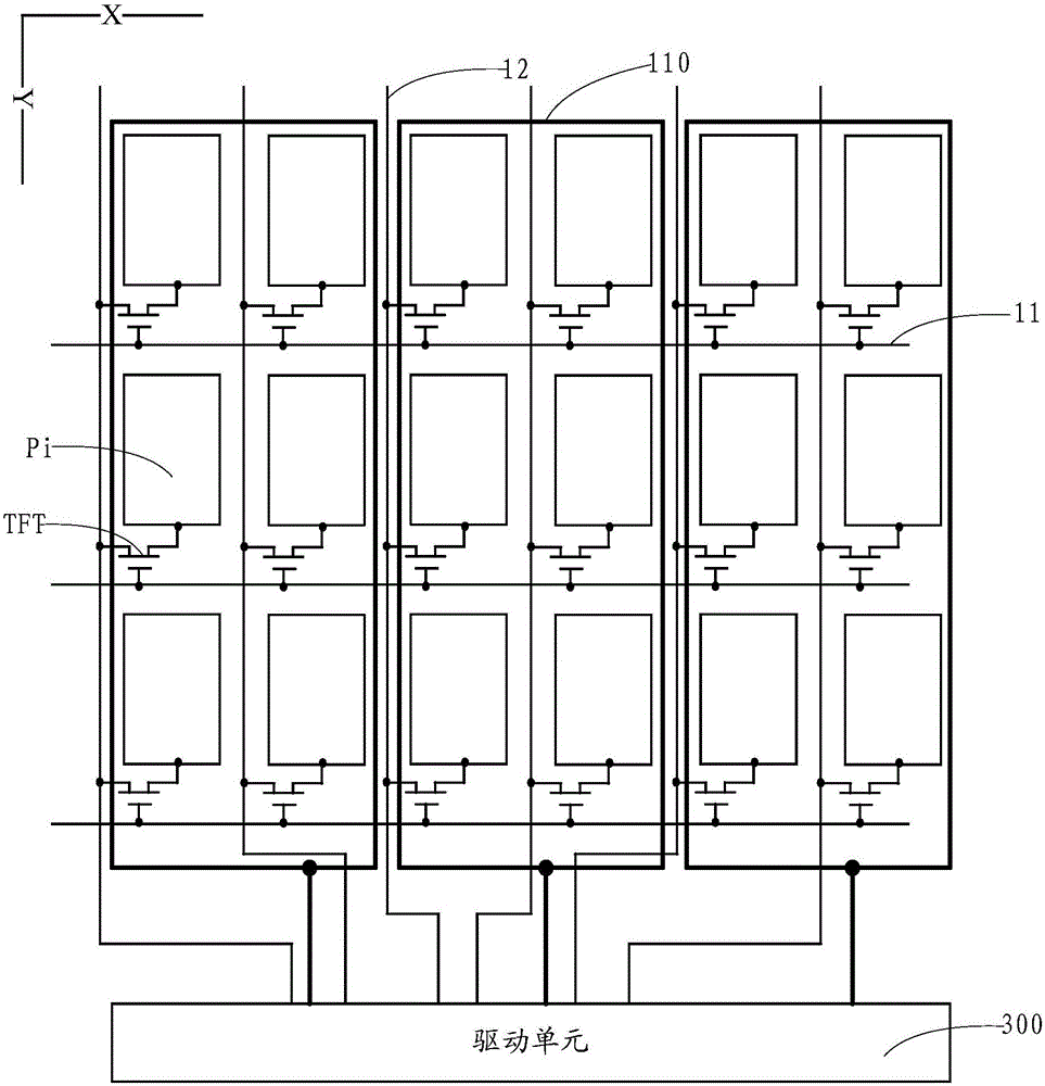
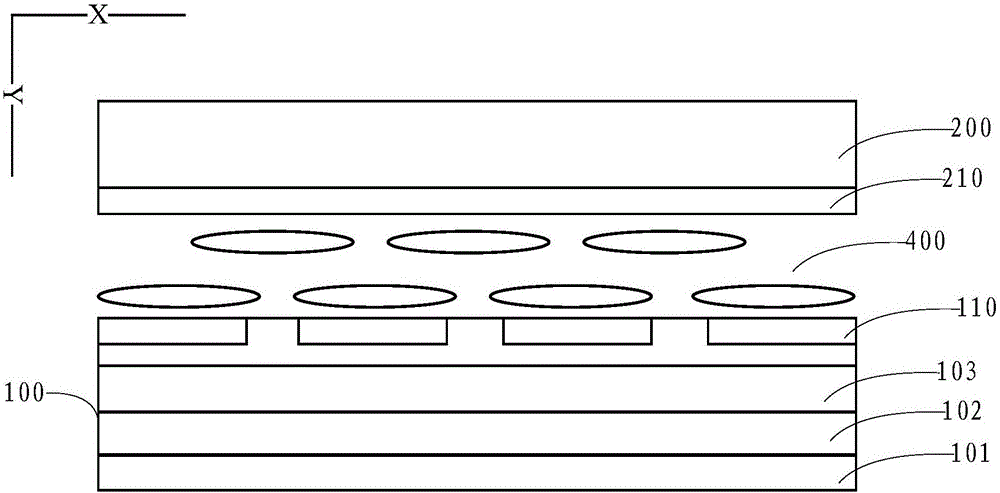
[0047] combine Figure 1a and Figure 1b as shown, Figure 1a It is a schematic top view of a touch display panel provided in Embodiment 1 of the present application, Figure 1b A cross-section schematic diagram of a touch display panel provided in Embodiment 1 of the present application, wherein the touch display panel includes:
[0048] The array substrate 100 and the color filter substrate 200 are arranged oppositely, wherein the array substrate 200 includes a pixel unit array composed of a plurality of pixel units, each pixel unit includes a pixel electrode Pi, and all the pixel electrodes Pi are along the The first direction X is arranged into a plurality of pixel electrode columns, and the second direction Y is arranged into a plurality of pixel electrode rows, the first direction X and the second direction Y intersect, and the touch display panel further includes:
[0049] A plurality of touch emitter electrodes 110 arranged along the first direction X and multiplexed ...
Embodiment 2
[0065] Embodiment 2 of the present application also provides a touch display panel, combined with Figure 4a and Figure 4b as shown, Figure 4a It is a schematic top view of a touch display panel provided in Embodiment 2 of the present application, Figure 4b A cross-section diagram of a touch display panel provided in Embodiment 2 of the present application, wherein the touch display panel includes:
[0066] The array substrate 500 and the first substrate 600 are arranged oppositely, wherein the array substrate 500 includes a pixel unit array composed of a plurality of pixel units, each pixel unit includes an anode An, and all the anodes An are arranged along the first A plurality of anode columns are arranged in the direction X, and a plurality of anode rows are arranged in the second direction Y, the first direction X and the second direction Y intersect, and the touch display panel further includes:
[0067] A plurality of touch emitter electrodes 510 arranged along th...
Embodiment 3
[0083] In addition, Embodiment 3 of the present application also provides a touch display device, the touch display device includes the touch display panel provided in any one of the above embodiments, such as Figure 7 As shown, the touch display device is a touch screen mobile phone 701 . In addition, the touch display device in the present invention can also be a notebook computer, a television, a vehicle display device, etc., without limitation.
[0084] Wherein, the touch display device provided in Embodiment 3 of the present application may be a liquid crystal touch display device, and may also be an organic light-emitting touch display device, which is not specifically limited in this application.
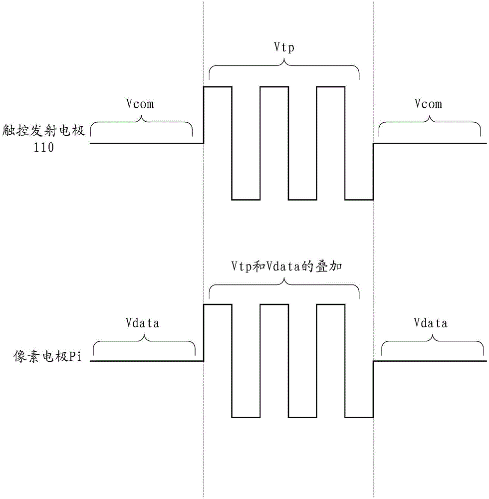
[0085] Embodiments of the present application provide a touch display panel, a driving method, and a touch display device, wherein the touch emitter electrode is multiplexed with a common electrode layer or a cathode layer, and when the display panel is driven and a frame is...
PUM
 Abstract
Description
Claims
Application Information