Scanning method with adjustable sampling frequency and touch device using the same

a capacitive touch and sampling frequency technology, applied in the direction of instruments, computing, electric digital data processing, etc., can solve the problems of inaccurate capacitance values, low report rate, unsmooth operation, etc., and achieve the effect of increasing the report rate of the sensing uni

Inactive Publication Date: 2015-03-19
ELAN MICROELECTRONICS CORPORATION
View PDF11 Cites 7 Cited by
  • Summary
  • Abstract
  • Description
  • Claims
  • Application Information

AI Technical Summary

Benefits of technology

[0033]After the touch device performs an analog-to-digital conversion (ADC) calibration procedure, the receiving unit automatically generates a capacitance offset corresponding to each sensor trace connected thereto. Such capacitance offset varies with the RC load value of the sensor traces. Hence, prior to formal scanning, the present invention pre-scans the touch device once first to acquire capacitance offsets corresponding to sensors traces in the first-axis direction or the second-axis direction. Upon formal scanning, the receiving unit configures a sampling frequency of a corresponding driven sensor trace according to the capacitance offset of the driven sensor trace. As to the sensor traces with lower RC load values, higher sampling frequencies are used to receive the sensed capacitance values of the sensor traces. As to the sensor traces with higher RC load values, lower sampling frequencies are used to receive the sensed capacitance values of the sensor traces, thereby fulfilling the goal of automatically adjusting sampling frequency and increasing a report rate of the sensing unit.

Problems solved by technology

The lowered sampling frequency leads to a lower report rate, which causes unsmooth operation.
However, if the sampling frequency is not lowered, there is a likelihood that incorrect capacitance values are received when the capacitors intersected by the first traces and the second traces are not yet fully charged to the saturation state or discharged to zero voltage.
However, the solution has the shortcoming of being time-consuming in operation.

Method used


Image

  • Scanning method with adjustable sampling frequency and touch device using the same
  • Scanning method with adjustable sampling frequency and touch device using the same
  • Scanning method with adjustable sampling frequency and touch device using the same

Examples


Embodiment Construction

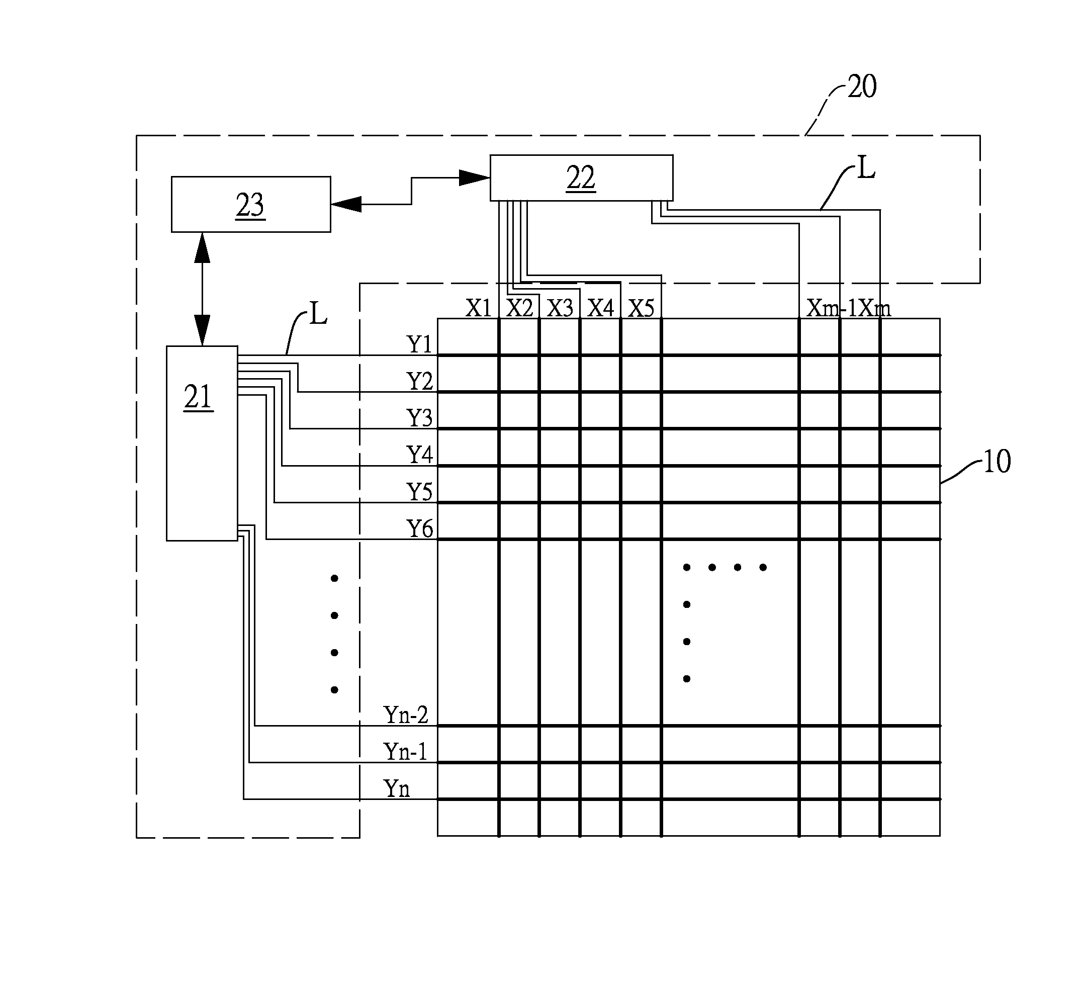
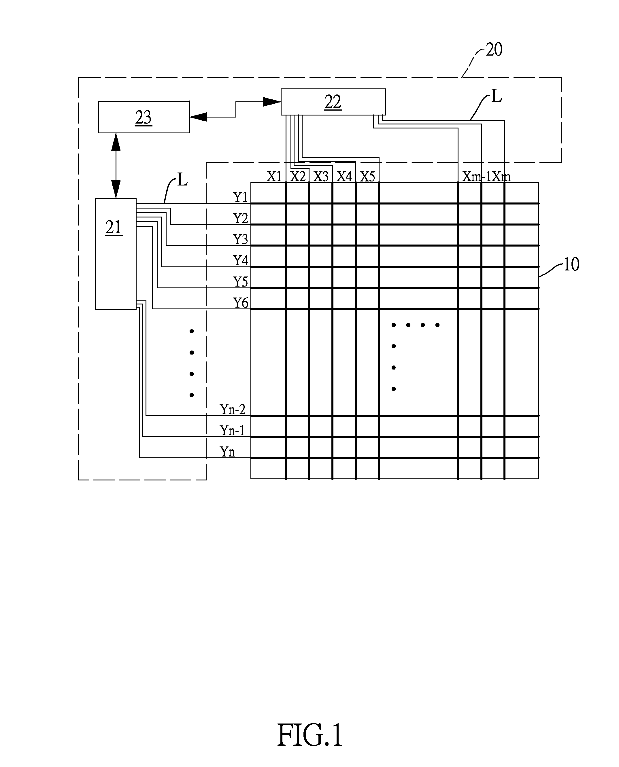
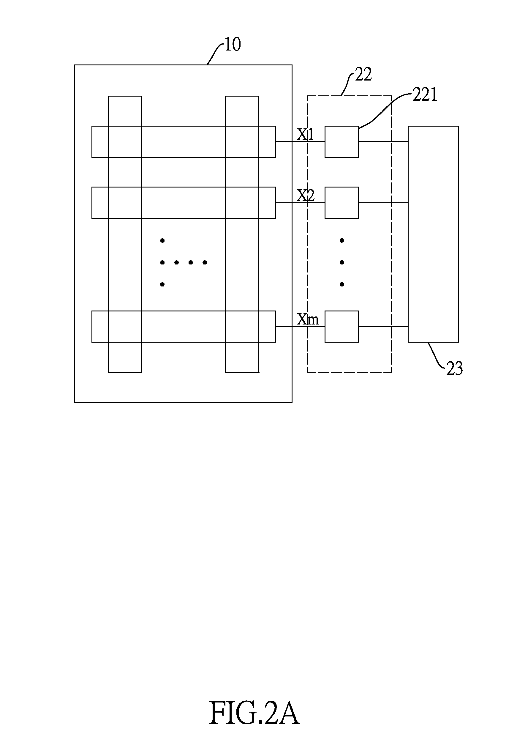
[0048]With reference to FIG. 1, a touch device in accordance with the present invention has a sensing unit 10 and a scanning circuit 20. The scanning circuit 20 has a driving unit 21, a receiving unit 22 and a control unit 23 electrically connected to the driving unit 21 and the receiving unit 22. With reference to FIGS. 2A and 3A, an embodiment of the receiving unit 22 has multiple receivers 221 respectively connected to multiple second traces X1˜Xm of the sensing unit 10 aligned in a second-axis direction. Each receiver 221 has a comparator 222, an analog-to-digital converter (ADC) 223, and a variable capacitance compensation circuit 224. One input terminal of the comparator 222 is connected to one end of one of the second traces X1˜Xm and the variable capacitance compensation circuit 224. An output terminal of the comparator 222 is connected to the control unit 23 through the ADC 223 to convert a sensed capacitive signal of the second trace X1˜Xm into a digital capacitance value ...


PUM


Abstract

A scanning method with adjustable sampling frequency includes steps of pre-scanning a sensing unit of a touch device to acquire capacitance offsets of sensor traces of the sensor unit aligned in at least one of a first-axis direction and a second-axis direction, determining sampling frequencies according to the capacitance offsets of the respective driven sensor traces, and sampling the sensing unit with the determined sampling frequencies. As the capacitance offsets reflect RC load values corresponding to the sensor traces in the first-axis direction, the sampling frequencies can be adjusted according to the actual RC load values when the sensing unit is scanned to receive sensed signals, thereby effectively raising a report rate of touch events.

Description

BACKGROUND OF THE INVENTION[0001]1. Field of the Invention[0002]The present invention relates to a scanning method of a capacitive touch device, and more particularly to a scanning method with adjustable sampling frequency and a touch device using the scanning method.[0003]2. Description of the Related Art[0004]Capacitive touch device detects a location of an object, such as a finger or a stylus, touching on the touch device by a capacitive variation of corresponding sensor traces. To ensure a correct sensing of capacitive variation caused by the object touching the sensor traces, capacitive touch device usually acquires a reference value through an analog-to-digital conversion (ADC) calibration procedure when being turned on or awakened from a hibernation state. The reference value is taken to determine where the object is actually on the capacitive touch device upon subsequent scanning.[0005]With reference to FIG. 10, a conventional mutual capacitance touch device has a sensing un...

Claims


Application Information

Patent Timeline
Patent Type & Authority Applications(United States)
IPC IPC(8): G06F3/044
CPCG06F3/044G06F3/0418G06F3/04166G06F3/0446
Inventor HUANG, JUNG-SHOUWU, CHIA-MU
Owner ELAN MICROELECTRONICS CORPORATION
Why Eureka
Try Eureka