
Pulse width control device and method based on constant conduction time

A pulse width control, constant on-time technology, applied in output power conversion devices, measurement devices, control/regulation systems, etc., can solve problems such as inflexibility

Active Publication Date: 2017-02-01
MEDIATEK INC
View PDF6 Cites 3 Cited by
  • Summary
  • Abstract
  • Description
  • Claims
  • Application Information

AI Technical Summary

Problems solved by technology

However, setting the on-time pulse width with the fixed value is inflexible since the events of the transients are not always the same

Method used


Image

  • Pulse width control device and method based on constant conduction time
  • Pulse width control device and method based on constant conduction time
  • Pulse width control device and method based on constant conduction time

Examples


Embodiment Construction

[0021] The following descriptions are preferred embodiments for implementing the present invention. The following examples are only used to illustrate the technical characteristics of the present invention, and are not intended to limit the scope of the present invention. Certain terms are used throughout the specification and claims to refer to particular elements. It should be understood by those skilled in the art that manufacturers may use different terms to refer to the same element. The specification and claims do not use the difference in name as the way to distinguish components, but the difference in function of the components as the basis for the difference. The terms "element", "system" and "apparatus" used in the present invention may be a computer-related entity, where the computer may be hardware, software, or a combination of hardware and software. The terms "comprising" and "including" mentioned in the following description and claims are open terms, so they ...


PUM


Abstract

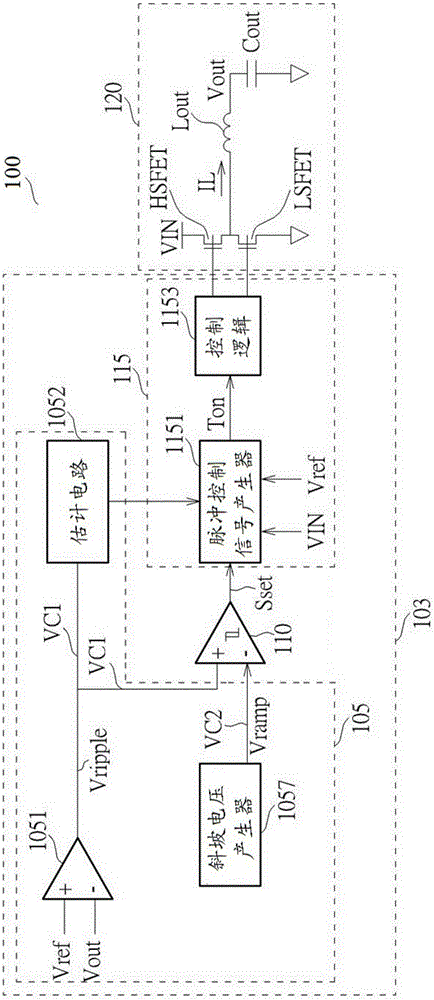
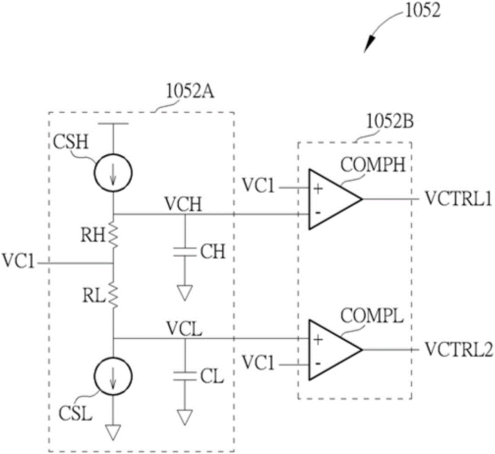
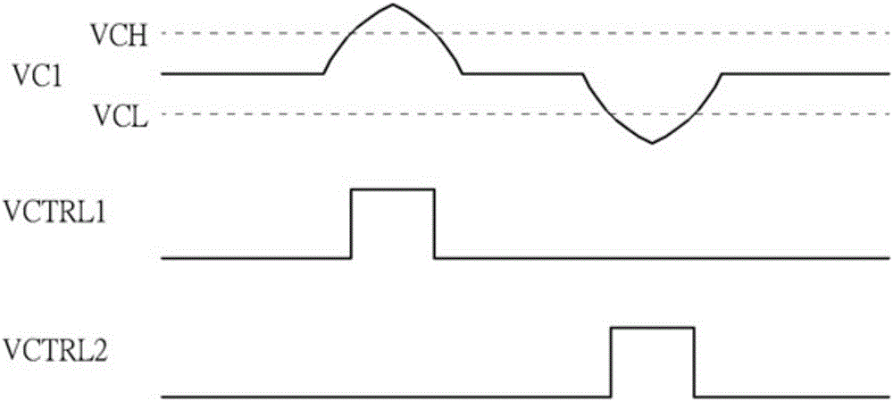
The invention discloses a pulse width control device and method based on constant conduction time. The pulse width control device and method based on constant conduction time are capable of detecting a transient event of a voltage converter (100) includes a specific comparator (110), a logic circuit (115), and a controller (105). The specific comparator (110) generates a logic control signal to the logic circuit (115) according to two resultant signals (VC1, VC2) of the controller (105). The logic circuit (115) generates a pulse control signal (Ton) with an on-time pulse width to charge an output capacitor according to the logic control signal. The controller (105) generates the two resultant signals (VC1, VC2) to the specific comparator (110) by generating a voltage ramp signal (Vramp) and amplifying an output voltage ripple signal (Vripple) based on a reference voltage (Vref), and detects the transient event to dynamically adjust the on-time pulse width of the pulse control signal (Ton) according to the amplified output voltage ripple signal (VC1).

Description

technical field [0001] The present invention relates to a voltage converter solution, more particularly, to a device and method based on constant on-time pulse width control used in a voltage converter, and has a fast transient State responsiveness and the flexibility of adaptively adjusting the on-time pulse width in response to the occurrence of transient events. Background technique [0002] Generally speaking, conventional constant on-time controllers are often limited by the small equivalent series resistor (ESR) of their output capacitors. Because the ESR is too small, conventional controllers cannot effectively reflect / detect the ripple of the output voltage and are difficult to detect or respond to the occurrence of transient events. To improve this problem, some traditional schemes have been proposed. However, some of these conventional solutions are still unable to effectively detect or respond to the occurrence of transient events. Furthermore, another part of ...

Claims


Application Information

Patent Timeline
Patent Type & Authority Applications(China)
IPC IPC(8): H02M3/158
CPCH02M3/158H02M3/156H02M1/0025H02M3/1566G01R19/16585H02M1/0045H02M1/0067
Inventor 黄华强
Owner MEDIATEK INC
Learn More