An energy-saving particle distribution device

A distribution device and particle technology, applied in the field of mechanical equipment, can solve the problems of waste of heat and water resources, and achieve the effect of less energy consumption and good heat exchange effect

Active Publication Date: 2018-10-23
XI AN JIAOTONG UNIV
View PDF6 Cites 0 Cited by
  • Summary
  • Abstract
  • Description
  • Claims
  • Application Information

AI Technical Summary

Problems solved by technology

After various water quenching processes, only 10% of the total heat of the slag is recovered, and the rest of the heat is discharged into the atmosphere with water vapor, resulting in waste of heat and water resources

Method used


Image

  • An energy-saving particle distribution device
  • An energy-saving particle distribution device
  • An energy-saving particle distribution device

Examples


Embodiment Construction

[0014] The present invention will be described in further detail below in conjunction with the accompanying drawings and specific embodiments.

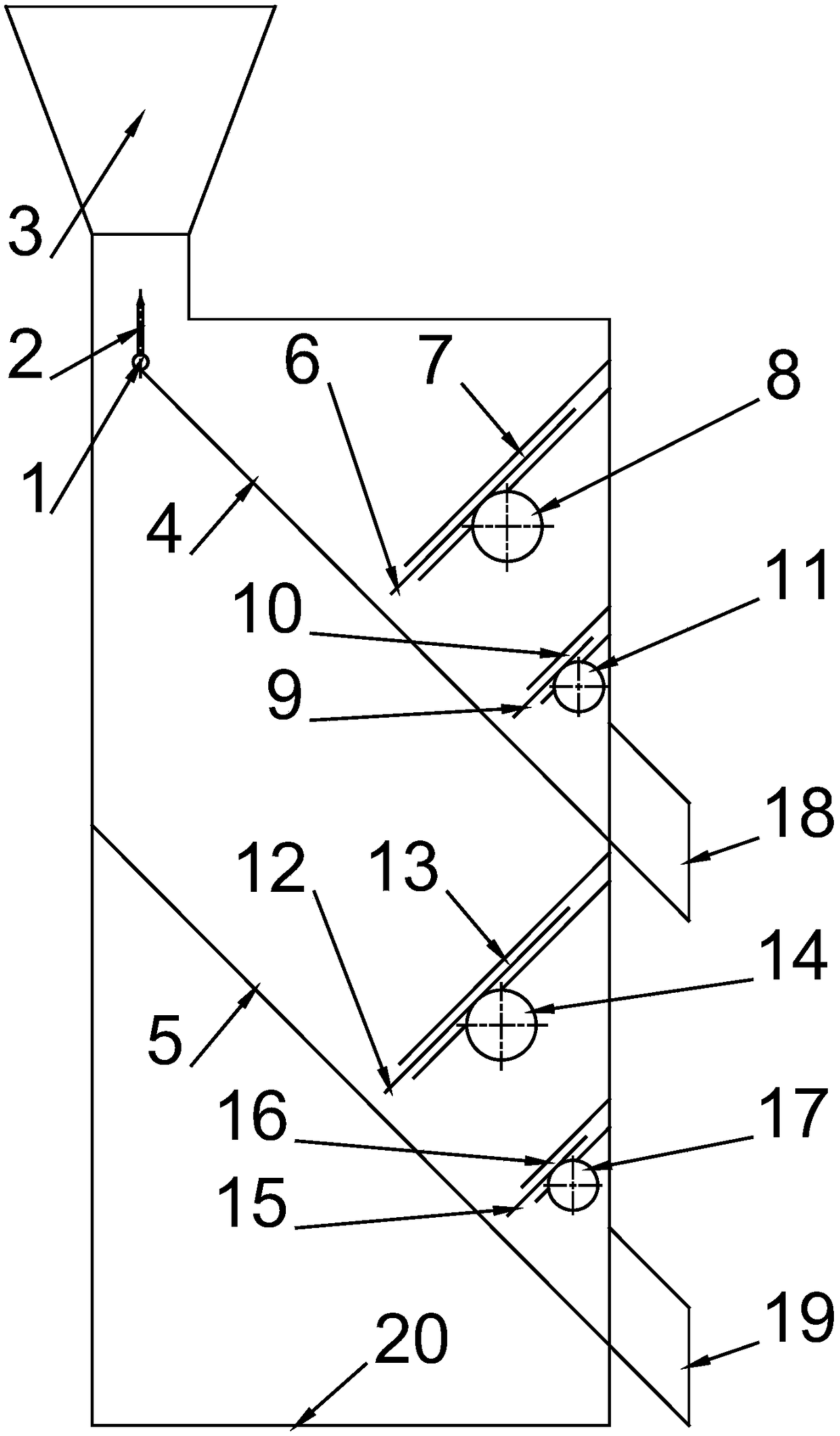
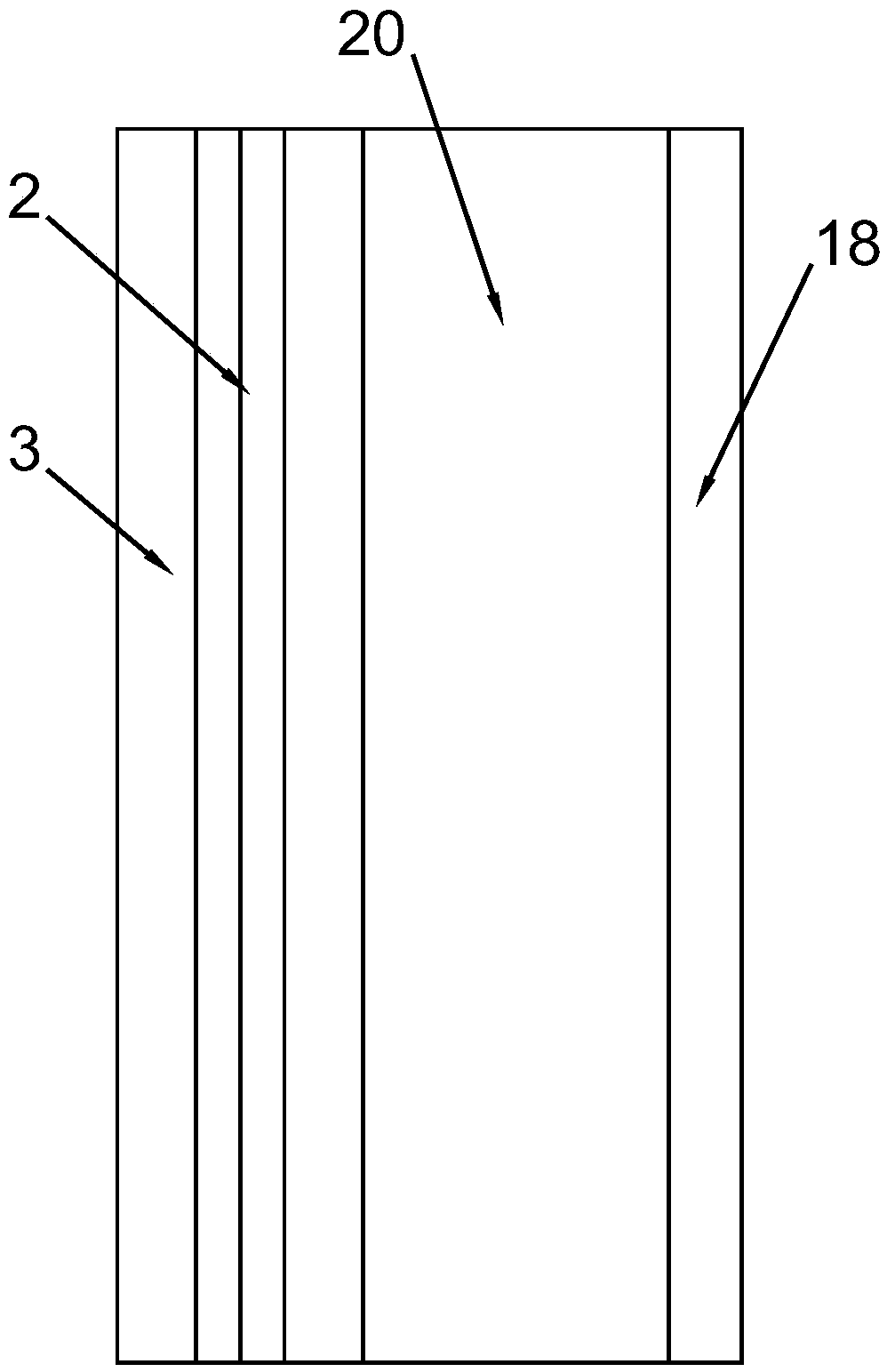
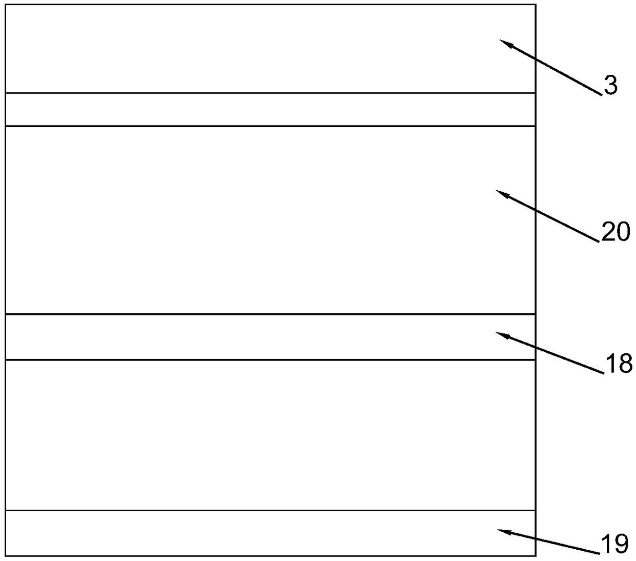
[0015] like figure 1 , figure 2 and image 3 As shown, an energy-saving particle distribution device includes a rotating shaft 1, a rotating plate 2, a funnel 3, an upper partition 4, a lower partition 5, a movable baffle a6, a fixed baffle a7, a gear a8, a movable baffle b9, Fixed baffle b10, gear b11, movable baffle c12, fixed baffle c13, gear c14, movable baffle d15, fixed baffle d16, gear d17, upper outlet 18, lower outlet 19, and housing 20.

[0016] like figure 1 As shown, the funnel 3 is a symmetrical structure, the rotating shaft 1 is located on the symmetrical plane of the funnel 3, and the rotating plate 2 can adjust the rotation angle under the drive of the rotating shaft 1. , will drop to the upper partition 4 and the lower partition 5 arranged obliquely on both sides of the rotating plate 2 respectively. The length ...


PUM


Abstract

An energy-saving particle distributing device comprises a rotating shaft, a rotating plate, a funnel, an upper partition plate, a lower partition plate, movable baffles, fixed baffles, gears, an upper outlet, a lower outlet and a shell. The energy-saving particle distributing device is characterized in that the funnel is of a symmetrical structure, the rotating shaft is located on the symmetrical sections of the funnel, the rotating plate can adjust the rotation angle under the drive of the rotating shaft, and after entering the shell from the funnel, particles fall to the inclined upper partition plate and the inclined lower partition plate correspondingly from the two sides of the rotating plate due to partition of the rotating plate; and the movable baffles are provided with racks, and the movable baffles can be driven by the gears to move up and down along hollow structures of the fixed baffles so that the sizes of the gaps between the movable baffles and the partition plates can be changed. According to the energy-saving particle distributing device, the fallen particles are distributed to the two partition plates through the rotating plate arranged below the funnel, distribution of the particles to the two partition plates can be adjusted through the control over the angle of the rotating plate and the sizes of the gaps between the movable baffles and the partition plates, reciprocating swinging is not needed, the energy consumption is small, and the structure is simple.

Description

technical field [0001] The invention relates to the field of mechanical equipment, in particular to an energy-saving particle distribution device. Background technique [0002] The energy consumption of the iron and steel industry accounts for about 35% of the total energy consumption of the industry. The temperature of blast furnace slag produced in the ironmaking process is 1450-1650°C, and the heat content of blast furnace slag is about 1.70-1.87GJ / t, which is equivalent to 0.058-0.06 tons of standard coal. Calorific value. The total amount of sensible heat of slag is huge, and the recovery of slag waste heat is of great significance to energy saving and emission reduction in the iron and steel industry, and to improve energy utilization efficiency. At present, domestic metallurgical enterprises mainly use water quenching process for high temperature slag. Only 10% of the total heat of the slag is recovered through various water quenching processes, and the remaining he...

Claims


Application Information

Patent Timeline
Patent Type & Authority Patents(China)
IPC IPC(8): C21B3/06
CPCC21B3/06Y02W30/50
Inventor 吴东垠孔伟佳
Owner XI AN JIAOTONG UNIV
Why Eureka
Try Eureka