
Stress device and fight fitness machine

A fitness machine and tension technology, applied in the field of fitness equipment, can solve the problems of indeterminate contraction direction and irregular distortion, and achieve the effect of controllable contraction direction

Inactive Publication Date: 2017-02-15
陈亮
View PDF7 Cites 0 Cited by
  • Summary
  • Abstract
  • Description
  • Claims
  • Application Information

AI Technical Summary

Problems solved by technology

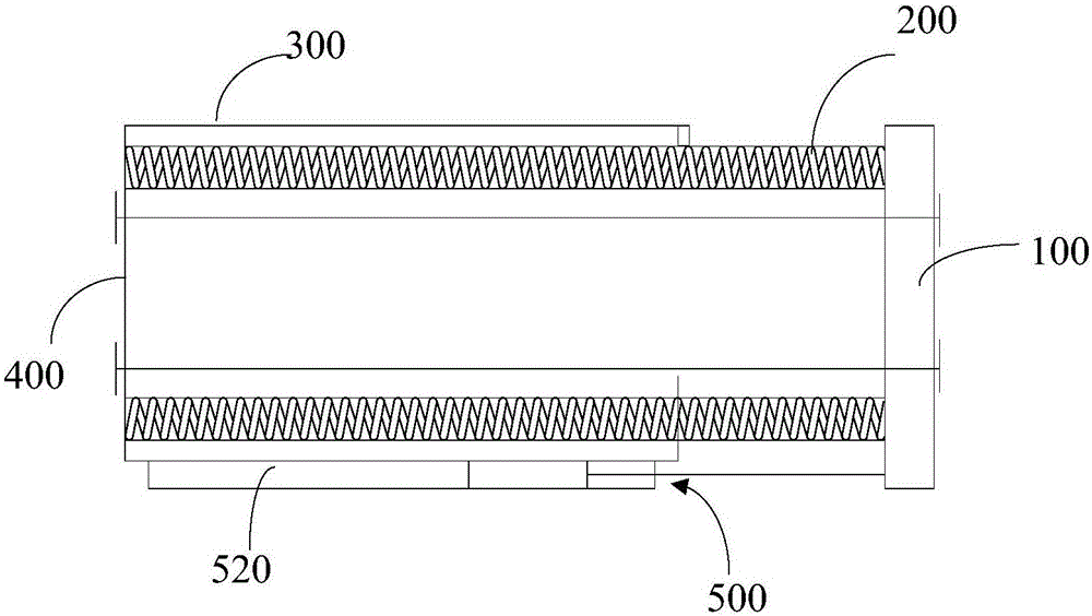
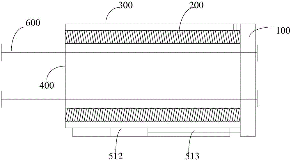
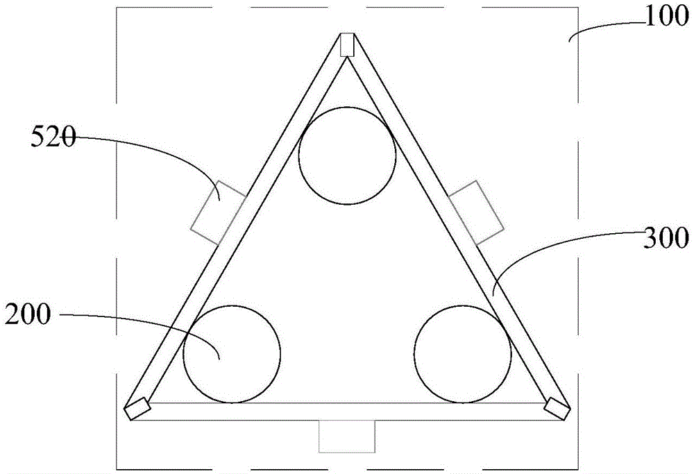
[0003] The force-bearing device is an indispensable part of fighting equipment. The existing force-bearing device usually includes a force-bearing panel and an elastic element. However, when the force-bearing panel is stressed, the direction of contraction is uncertain, and there is a technical problem of irregular distortion.

Method used


Image

  • Stress device and fight fitness machine
  • Stress device and fight fitness machine
  • Stress device and fight fitness machine

Examples


Embodiment 1

[0031] An embodiment of the present invention provides a force-bearing device for a boxing fitness machine, such as figure 1 , 2 , 3, including: a force-bearing panel 100 arranged in sequence along the force-bearing direction, an elastic element 200 and a back frame 300 arranged on the column 700 of the boxing fitness machine, and the back frame 300 has a backboard 400 near the end of the column 700; The two ends of the elastic element 200 abut against the back plate 400 and the stressed panel 100 respectively; the back frame 300 and the stressed panel 100 are movably connected through the limit assembly 500, which is used to limit the elastic direction of the stressed panel 100 relative to the back frame 300 The expansion and contraction direction of the element 200 moves.

[0032] A force-bearing device provided by an embodiment of the present invention is used in a boxing fitness machine, including: a force-bearing panel 100, an elastic element 200, a back frame 300, and a...

Embodiment 2

[0058] This embodiment provides a boxing fitness machine, such as Figure 5 As shown, it includes a column 700 and the above-mentioned force-bearing device, and the back frame 300 of the force-bearing device is located on the column 700 .

[0059] In the boxing fitness machine provided by the embodiment of the present invention, since the above-mentioned force-bearing device is provided on the column of the boxing fitness machine, when the user performs boxing fitness, the technical effect of the controllable contraction direction of the force-bearing panel is achieved.

[0060] There can be multiple stress panels on the boxing fitness machine, such as Figure 5 As shown in the figure, the front load-bearing panels are used to withstand the fighter's straight punches, while the side load-bearing panels are used to withstand the fighter's uppercuts.

[0061] For the boxing fitness machine, the heights of the bodybuilders are not the same, and for the force-bearing device that ...


PUM


Abstract

The invention provides a stress device and a fight fitness machine, and relates to the technical field of fitness apparatuses. The stress device comprises a stress panel, an elastic element and a back framework which are sequentially arranged in the stress direction, wherein the back framework is arranged on a vertical column of the fight fitness machine; a back plate is arranged at one end, near the vertical column, of the back framework; both ends of the elastic element are respectively abutted with the back plate and a stress surface; the back framework and the stress panel are movably connected by a limiting assembly to limit the movement of the stress panel corresponding to the back framework in the telescopic direction of the elastic element. The stress device has the advantages that the technical problem of uncertainty of shrinkage direction after stress is provided by the stress device is solved, and the technical effect of controllable stress movement direction of the stress device is realized.

Description

technical field [0001] The invention relates to the technical field of fitness equipment, in particular to a force-bearing device and a boxing fitness machine. Background technique [0002] Fighting, as a fitness sport, can not only exercise the body, lose weight, but also release stress, and it has been favored by more and more people. With people's demand for indoor fitness, a kind of equipment for indoor fitness fighting Came into being. [0003] The force-bearing device is an indispensable part of fighting equipment. The existing force-bearing device usually includes a force-bearing panel and an elastic element. However, when the force-bearing panel is stressed, the contraction direction is indeterminate, and there is a technical problem of irregular distortion. Contents of the invention [0004] The purpose of the present invention is to provide a force-bearing device and a boxing fitness machine, so as to reduce the technical problem in the prior art that the contra...

Claims


Application Information

Patent Timeline
IPC IPC(8): A63B69/32A63B71/06
CPCA63B69/32A63B71/0622A63B2244/10
Inventor 陈亮
Owner 陈亮
Learn More