Removing device of tail coil of cold-rolling unit and tail coil removing method thereof

A tail rolling and removal technology, which is applied in the field of metallurgical rolling and cold rolling mills, can solve problems affecting production rhythm and work efficiency, and achieve rapid and effective removal, improve work efficiency, and fast production rhythm

Active Publication Date: 2017-02-15
MCC SFRE HEAVY IND EQUIP
View PDF7 Cites 1 Cited by
  • Summary
  • Abstract
  • Description
  • Claims
  • Application Information

AI Technical Summary

Problems solved by technology

The traditional tail coil removal method is to use the coil trolley to transport the tail coil, and then use the crane to lift the tail coil to the waste coil area. Generally, the tasks of the coil transport trolley and the crane in the cold rolling workshop are very busy. , so in practice, the original method of tail roll removal seriously affected the production rhythm and work efficiency

Method used


Image

  • Removing device of tail coil of cold-rolling unit and tail coil removing method thereof

Examples


Embodiment Construction

[0022] The present invention will be described in detail below in conjunction with the accompanying drawings and specific embodiments.

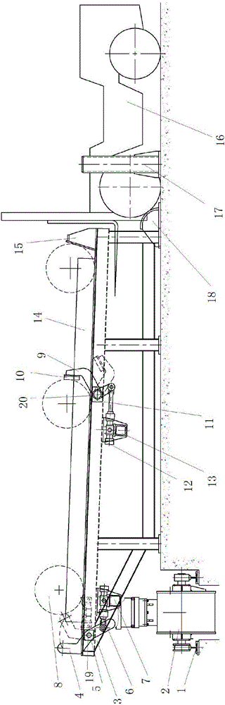
[0023] The invention provides a device for removing tail coils of a cold rolling mill, such as figure 1 As shown, the bracket 3 is included, the top of the bracket 3 is a slope, and the top of the bracket 3 is sequentially provided with a rolling plate 4, a coiling plate 9 and a baffle 15 from high to low, and the baffle 15 is close to the lowest end of the bracket 3, and the rolling The plate 4 and the sub-rolling plate 9 are connected to the bracket 3 through the rotating shaft a19 and the rotating shaft b20 respectively, and the rotating shaft a19 and the rotating shaft b20 are respectively connected with the push-roll hydraulic cylinder 6 and the split-roll hydraulic cylinder 12 through the hinge joint, and the push-roll hydraulic cylinder 6 and the split-roll hydraulic cylinder Roll hydraulic cylinder 12 is connected with support 3;

[...


PUM


Abstract

The invention discloses a removing device of a tail coil of a cold-rolling unit. The removing device of the tail coil of the cold-rolling unit comprises a support. The top of the support is an inclined face. A coil pushing plate, a coil partition plate and a baffle are arranged on the top of the support. The coil pushing plate and the coil partition plate are connected with the support through a rotating shaft a and a rotating shaft b correspondingly. The rotating shaft a and the rotating shaft b are connected with a coil pushing hydraulic cylinder and a coil partition hydraulic cylinder correspondingly through hinged joints. The coil pushing hydraulic cylinder and the coil partition hydraulic cylinder are both connected with the support. According to the removing device of the tail coil of the cold-rolling unit, the tail coil can be rapidly and effectively removed without the need for a crane. A tail coil removing method comprises the following steps that firstly, the tail coil is made to be identical with the top of the support in height; secondly, the coil pushing hydraulic cylinder drives the coil pushing plate to push the tail coil to reach the coil partition plate; and thirdly, the coil partition hydraulic cylinder is started, the coil partition plate is made to be unfolded, the tail coil rolls to the baffle along the support, and a forklift lifts the tail coil and conveys the tail coil to a workshop tail coil storage area. By the adoption of the tail coil removing method, the work efficiency is improved.

Description

technical field [0001] The invention belongs to the technical field of metallurgical rolling and cold rolling mills, and relates to a device for removing tail coils of a cold rolling mill, and also relates to a method for using the device to remove tail coils. Background technique [0002] In the cold rolling unit of a steel mill, in order to avoid affecting the product quality, the last few rounds of rolling and the strip head are usually cut off during the rolling process of the steel strip. These unqualified steel strips finally form a tail coil, so the tail coil The removal device is an indispensable equipment for every unit. The traditional tail coil removal method is to use the coil trolley to transport the tail coil, and then use the crane to lift the tail coil to the waste coil area. Generally, the tasks of the coil transport trolley and the crane in the cold rolling workshop are very busy. , so in practice, the original tail volume removal method has seriously affe...

Claims


Application Information

Patent Timeline
Patent Type & Authority Applications(China)
IPC IPC(8): B21C47/24
CPCB21C47/24
Inventor 姬明刚史维青王煜张亮
Owner MCC SFRE HEAVY IND EQUIP
Why Eureka
Try Eureka