
Cable release device for submersible

A disengagement device and submersible technology, applied in the directions of transportation and packaging, underwater operation equipment, ships, etc., can solve the problems of low reliability of the underwater hydraulic system, unfavorable safety guarantee of the submersible, complex structure, etc., and achieve disengagement. Reliable operation, simple structure and good versatility

Active Publication Date: 2018-06-19
CHINA SHIP SCIENTIFIC RESEARCH CENTER (THE 702 INSTITUTE OF CHINA SHIPBUILDING INDUSTRY CORPORATION)
View PDF10 Cites 0 Cited by
  • Summary
  • Abstract
  • Description
  • Claims
  • Application Information

AI Technical Summary

Problems solved by technology

[0003] The existing cable release method generally uses an oil cylinder to push the cutter to cut the connecting cable. This cable release solution has a complex structure and a large volume, and the oil cylinder needs hydraulic drive, and the reliability of the underwater hydraulic system is low, which is not conducive to diving. device security

Method used


Image

  • Cable release device for submersible
  • Cable release device for submersible
  • Cable release device for submersible

Examples


Embodiment Construction

[0021] The specific implementation manner of the present invention will be described below in conjunction with the accompanying drawings.

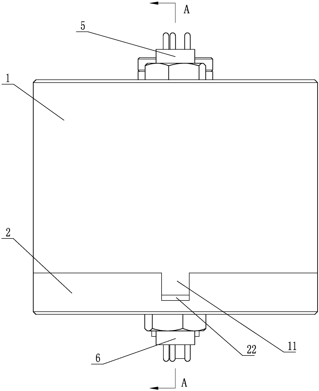
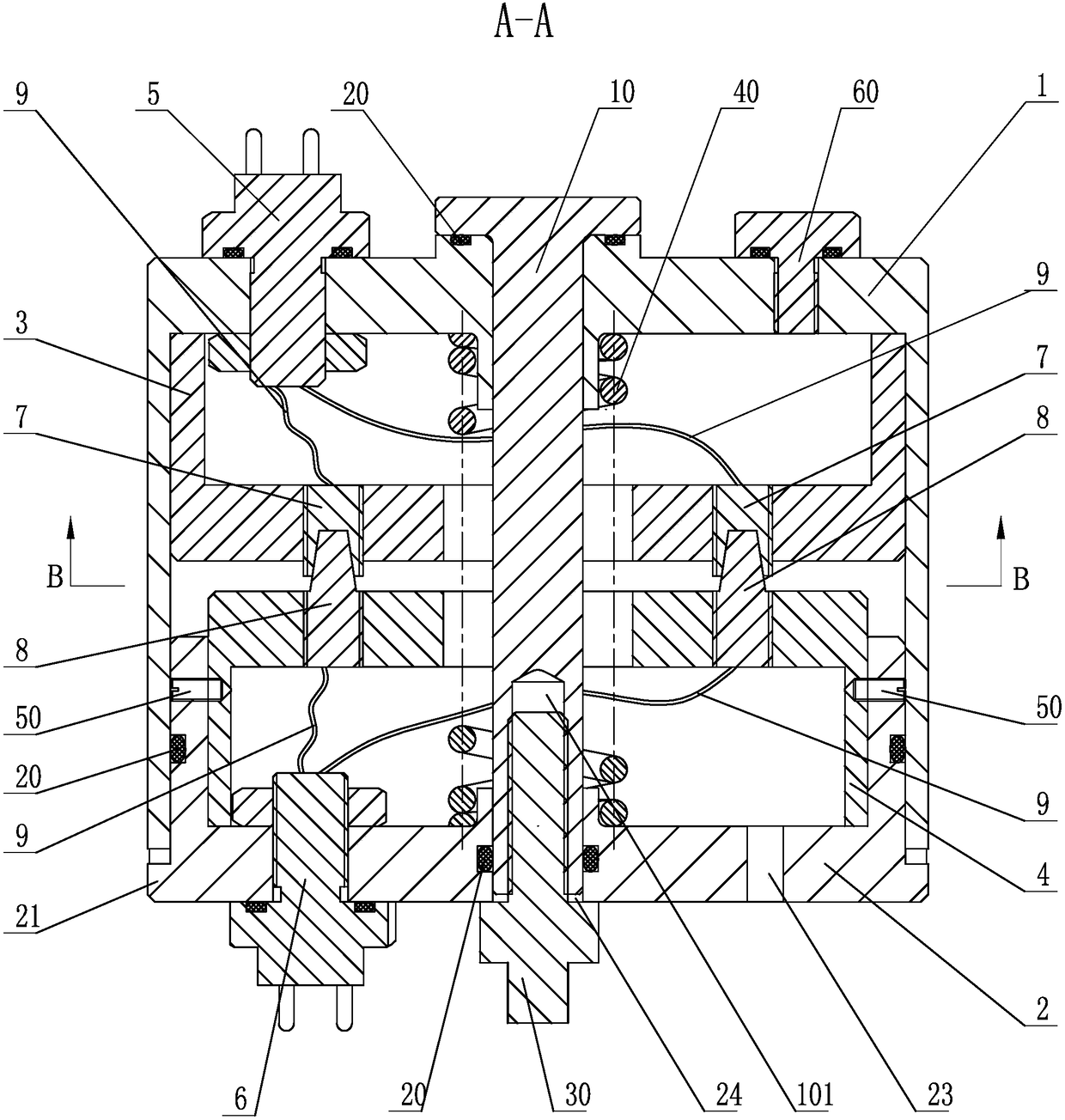
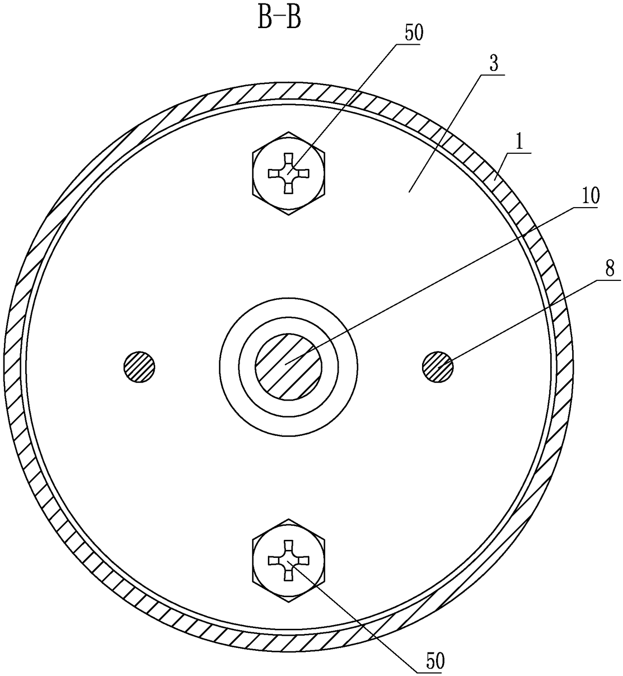
[0022] See figure 1 , figure 2 , the present invention includes an upper cylinder 1 and a lower cylinder 2, both of which have a cylinder structure with one end open, and the openings of the upper cylinder 1 and the lower cylinder 2 are opposite to each other and nested to form a sealed cavity. The upper installation cylinder 3 and the lower installation cylinder 4 are fixed in the sealed cavity. Both the upper installation cylinder 3 and the lower installation cylinder 4 have a cylinder structure with one end open. The openings of the upper installation cylinder 3 and the lower installation cylinder 4 face the upper cylinder respectively. The bottom of the cylinder 1 and the bottom of the lower cylinder 2; the bottom of the upper cylinder 1 and the lower cylinder 2 are respectively sealed and installed with an outlet watertight socket 5...


PUM


Abstract

The invention discloses a cable disengaging device for a submarine vehicle. The cable disengaging device comprises an upper barrel and a lower barrel; an opening of the upper barrel is opposite to an opening of the lower barrel, and is connected with the opening of the lower barrel in a sleeving manner for forming a sealing cavity; an upper mounting barrel and a lower mounting barrel are fixedly arranged in the sealing cavity; an opening is formed in one end of the upper mounting barrel and an opening is formed in one end of the lower mounting barrel; the opening of the upper mounting barrel and the opening of the lower mounting barrel face towards the barrel bottom of the upper barrel and the barrel bottom of the lower barrel respectively; an outlet watertight socket and an inlet watertight socket are mounted at the barrel bottom of the upper barrel and the barrel bottom of the lower barrel in a sealing manner respectively; female cable connectors and male cable connectors are fixedly mounted at the barrel bottom of the upper mounting barrel and the barrel bottom of the lower mounting barrel respectively; the female cable connectors are connected with the outlet watertight socket through wires; the male cable connectors are connected with the inlet watertight socket through the wires; a drawbar penetrates through the upper barrel, the upper mounting barrel and the lower mounting barrel sequentially, and then stretches into a through hole in the barrel bottom of the lower barrel; the two ends of the drawbar are in sealing connection with the through hole and the barrel bottom of the upper barrel respectively; an opened internal thread groove is formed in the bottom of the drawbar, and is used for connecting with an explosive bolt; the drawbar is connected with a spring in a sleeving manner; and the two ends of the spring are abutted against the barrel bottom of the upper barrel and the barrel bottom of the lower barrel respectively. The cable disengaging device is reliable in disengaging operation and convenient to use.

Description

technical field [0001] The invention relates to the technical field of underwater emergency, in particular to a cable release device, in particular to a cable release device used on a submersible for connecting underwater operation equipment. Background technique [0002] Submersibles are important equipment for efficient exploration, scientific investigation, development operations, military detection and combat platforms. Submersibles usually carry some working tools driven by the submersible's own electricity for underwater operations. When these working tools are entangled underwater, they need to be separated from the submersible and discarded, and the submersible also needs to discard its own battery in an emergency box; at this time, it is necessary to disconnect the relevant connecting cables between the submersible and the working tool or between the submersible and the battery box. [0003] The existing cable release method generally uses an oil cylinder to push t...

Claims


Application Information

Patent Timeline
Patent Type & Authority Patents(China)
IPC IPC(8): B63C11/52
CPCB63C11/52
Inventor 刘浩胡震叶聪汤国伟
Owner CHINA SHIP SCIENTIFIC RESEARCH CENTER (THE 702 INSTITUTE OF CHINA SHIPBUILDING INDUSTRY CORPORATION)
Learn More