
An ammeter negative pressure non-destructive conveying device

A conveying device and negative pressure technology, applied in the field of negative pressure non-destructive conveying devices for electric meters, can solve the problems of uneven operation force, complicated operation, low work efficiency, etc., and achieve the effect of uniform operation force, solving complex operation and high work efficiency.

Active Publication Date: 2018-09-21
WUHAN SAN FRAN ELECTRONICS CO LTD
View PDF6 Cites 1 Cited by
  • Summary
  • Abstract
  • Description
  • Claims
  • Application Information

AI Technical Summary

Problems solved by technology

[0003] In order to solve the above problems, the present invention provides a negative pressure non-destructive conveying device for electric meters, which can solve the problems of manual dust removal and tin slag removal for smart electric meter casings, such as complex operation, high labor intensity, manual pick-up and placement, and uneven operating force , slow working speed and low working efficiency, it can realize the automatic guiding and conveying function of the dust removal and tin slag removal process of the smart meter shell, without manual operation, easy to operate, high working efficiency, and has negative pressure adsorption, non-destructive transportation, and strong operation Uniformity, fast working speed and high working efficiency

Method used

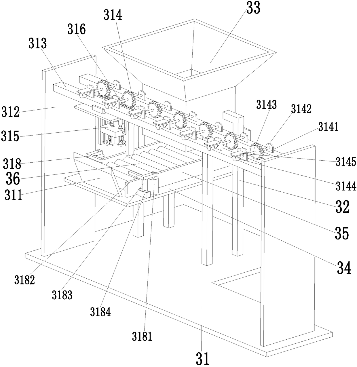
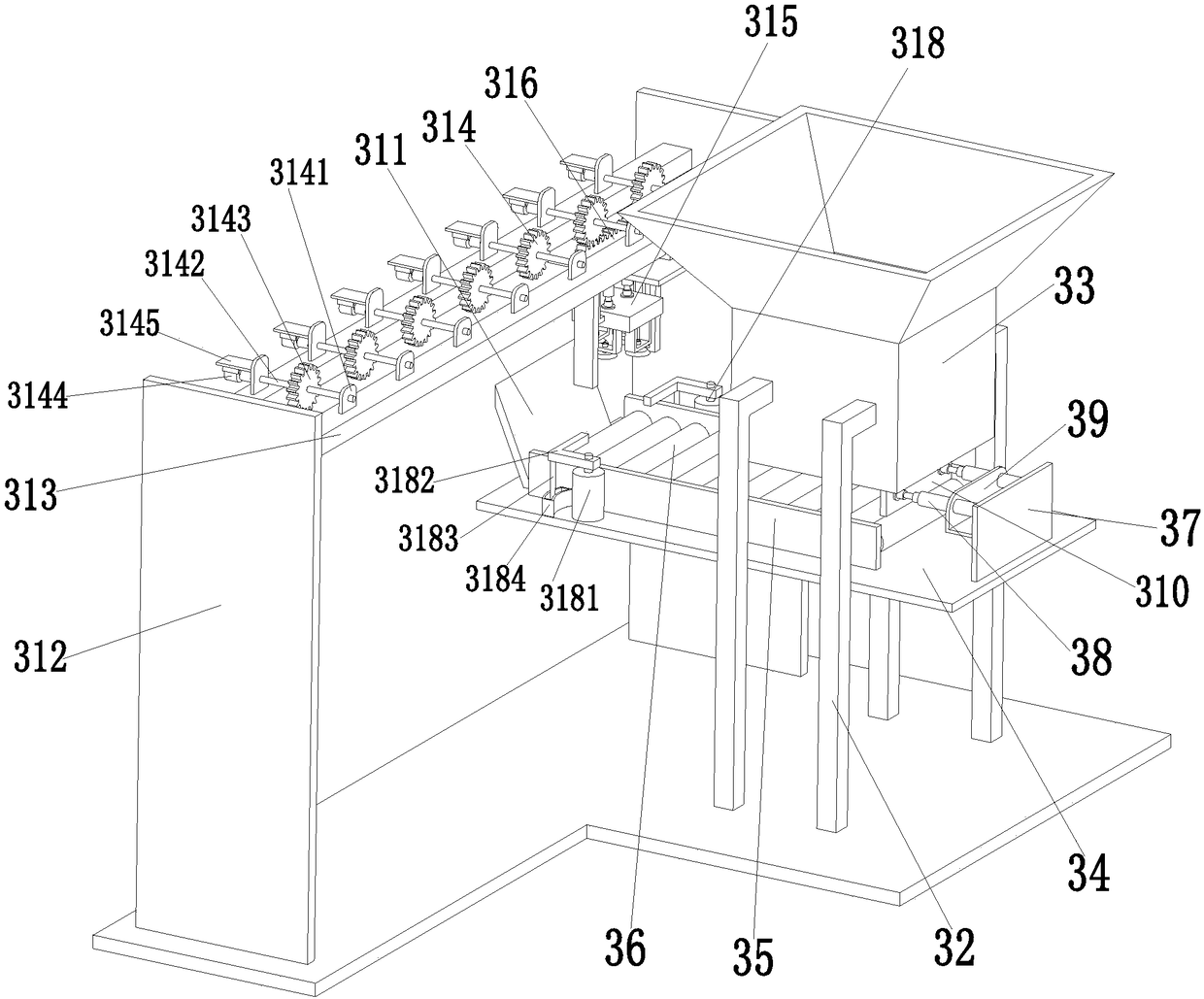
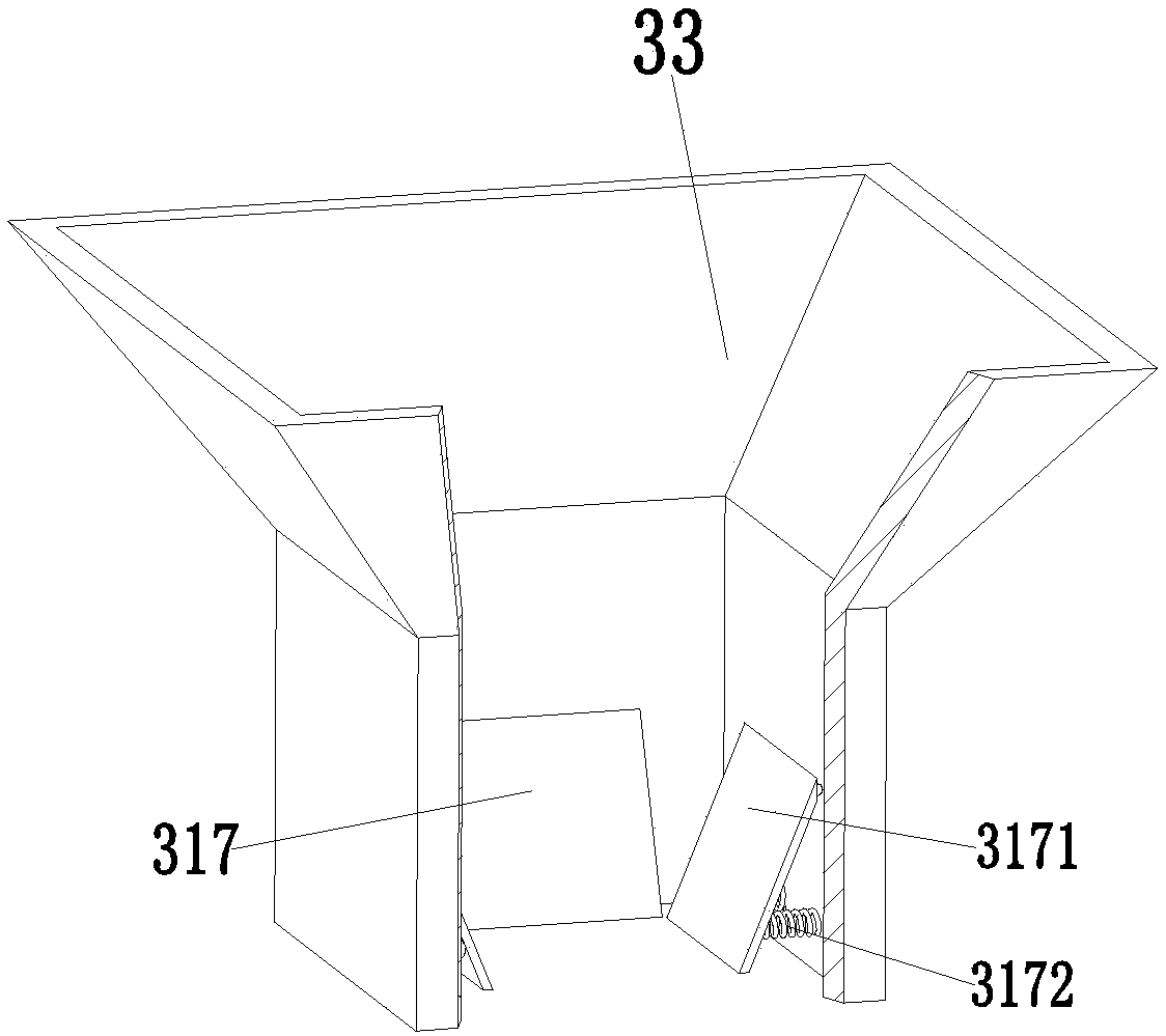

Image

  • An ammeter negative pressure non-destructive conveying device
  • An ammeter negative pressure non-destructive conveying device
  • An ammeter negative pressure non-destructive conveying device

Examples


Embodiment Construction

[0015] In order to make the technical means, creative features, goals and effects achieved by the present invention easy to understand, the present invention will be further described below in conjunction with specific illustrations.

[0016] Such as Figure 1 to Figure 4As shown, a negative pressure non-destructive conveying device for an electric meter includes a conveying support plate 31, four blanking pillars 32 are symmetrically installed on the conveying support plate 13, and a blanking frame 33 is welded between the upper ends of the four blanking pillars 32 , the four blanking pillars 32 play the role of evenly supporting the blanking frame 33, the middle part of the four blanking pillars 32 is equipped with a blanking support plate 34, and the upper end surface of the blanking support plate 34 is symmetrically provided with two baffles 35. The shell of the smart meter is generally a square shell structure. The shell of the smart meter enters the present invention thr...


PUM


Abstract

The invention relates to a negative-pressure lossless conveying device for electricity meters. The negative-pressure lossless conveying device comprises a conveying support plate, four discharging support columns are symmetrically mounted on the conveying support plate, a discharging frame is welded between the upper ends of the four discharging support columns, a discharging support plate is mounted on the middle portions of the four discharging support columns, and two baffles are symmetrically arranged on the upper end face of the discharging support plate; a first mounting plate is arranged on the rear side of the upper end face of the discharging support plate, two first hydraulic cylinders are symmetrically mounted on the first mounting plate, and the middle portions of the two first hydraulic cylinders are fixed to a first fixed plate; the first fixed plate is welded to the side wall of the first mounting plate, and a pushing plate is mounted at the top ends of the two first hydraulic cylinders through flanges; and a blocking plate is arranged on the front side of the upper end face of the discharging support plate. The negative-pressure lossless conveying device has an automatic guiding conveying function for the dust and tin slag removing process of shells of intelligent electricity meters, manual operation is not needed, operation is easy and convenient, and work efficiency is high; and the negative-pressure lossless conveying device has the advantages that negative-pressure adsorption and lossless conveying are achieved, operation force is uniform, the working speed is high, and work efficiency is high.

Description

technical field [0001] The invention relates to the technical field of electric meters, in particular to a negative pressure non-destructive conveying device for electric meters. Background technique [0002] The electric meter is the abbreviation of the electric energy meter, also known as the electric meter, the fire meter, the electric energy meter, the kilowatt-hour meter, and is an instrument used to measure electric energy. In order to adapt to the use of smart grid and new energy, in addition to the basic power consumption measurement function of traditional electric energy meters, smart meters also have two-way multi-rate metering functions, user-side control functions, and two-way data transmission modes in multiple data transmission modes. Intelligent functions such as communication functions and anti-stealing functions have been widely used due to their advantages such as low power consumption, long life, and accurate measurement. However, dust will be generated ...

Claims


Application Information

Patent Timeline
Patent Type & Authority Patents(China)
IPC IPC(8): B65G47/04B65G47/82B65G47/91
CPCB65G47/04B65G47/82B65G47/912
Inventor 王飞
Owner WUHAN SAN FRAN ELECTRONICS CO LTD
Learn More