Rotary compressor and electrical products including the same

A rotary compressor and compression chamber technology, applied in the field of compressors, can solve the problems of reduced volume change rate, small exhaust speed, large clearance volume, etc.

Active Publication Date: 2018-09-07
GREE ELECTRIC APPLIANCES INC
View PDF6 Cites 0 Cited by
  • Summary
  • Abstract
  • Description
  • Claims
  • Application Information

AI Technical Summary

Problems solved by technology

[0003] In the prior art, an exhaust port is usually provided on the inner wall of the cylinder on the side of the slide plate close to the compression chamber. However, in the existing scheme, the volume change rate of the element volume gradually decreases in the exhaust stage, and the exhaust velocity in the early stage of exhaust Larger, while the exhaust velocity is smaller in the later stage of exhaust
[0004] Using the exhaust port of the existing scheme, when the rolling piston rotates through the exhaust port, the residual high-pressure gas in the volume of the exhaust port will flow back into the suction chamber to cause suction backflow, and there will be a large clearance volume, resulting in repeated work and other efficiency loss problem
[0005] Moreover, in the early stage of exhaust, the exhaust velocity is relatively high, and the exhaust resistance is relatively large, resulting in low energy efficiency of the compressor.
[0006] Therefore, how to solve the problems of the compressor in the prior art, the large clearance volume in the exhaust structure, and the low energy efficiency of the compressor has become an important technical problem to be solved by those skilled in the art.

Method used


Image

  • Rotary compressor and electrical products including the same
  • Rotary compressor and electrical products including the same
  • Rotary compressor and electrical products including the same

Examples


Embodiment Construction

[0036] The purpose of this specific embodiment is to provide a rotary compressor, which can reduce the clearance volume and improve the energy efficiency of the compressor. The purpose of this specific embodiment is also to provide an electrical product including the above-mentioned rotary compressor.

[0037] Hereinafter, an embodiment will be described with reference to the drawings. In addition, the examples shown below do not limit the content of the invention described in the claims in any way. In addition, all the contents of the configurations shown in the following embodiments are not limited to be essential to the solution of the invention described in the claims.

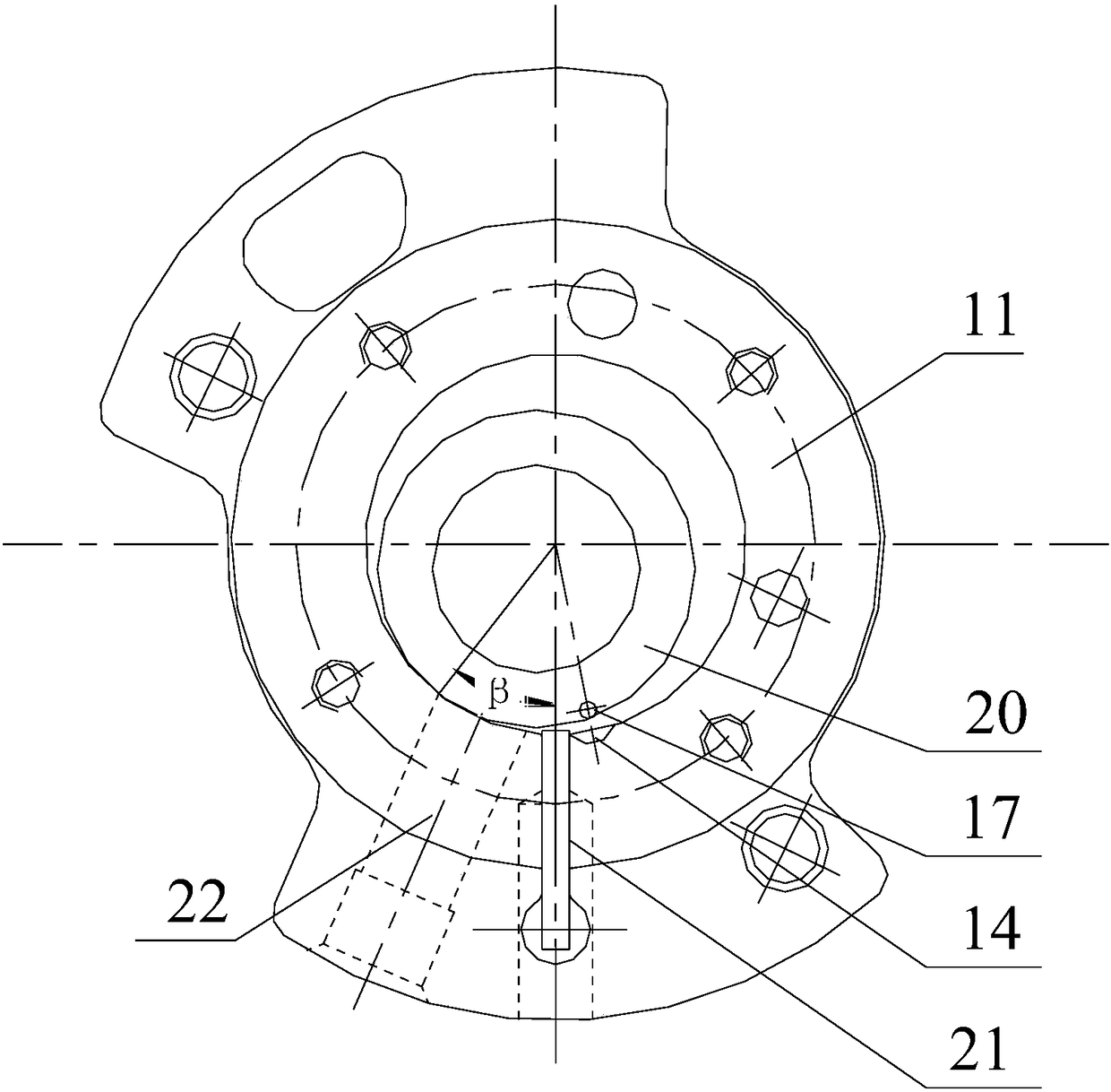
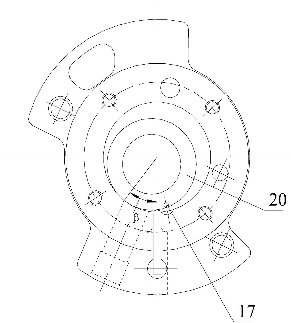
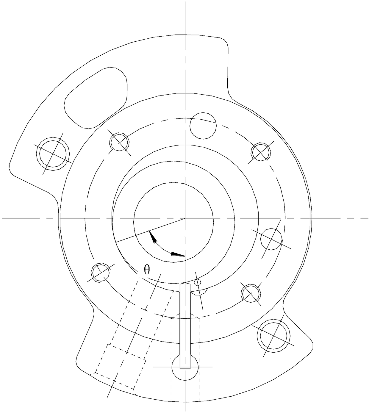
[0038] Please refer to Figure 1-Figure 10 , a rotary compressor provided in this embodiment includes a cylinder 11, an upper cover 12, a lower cover 13, a rolling piston 20 and a slide plate 21, wherein the rolling piston 20 extends into the inner cavity of the cylinder 11, and the slide plate 21 is arr...


PUM


Abstract

The invention discloses a rotational compressor and an electrical product comprising the rotational compressor. The rotational compressor comprises an air cylinder, an upper cover, a lower cover, a rolling piston and a sliding plate, wherein the upper cover and the lower cover are arranged at the two ends of the air cylinder, and the rolling piston and the sliding plate are arranged in the air cylinder. An inner cavity of the air cylinder is divided by the rolling piston and the sliding plate into a suction cavity and a compressing cavity. A main exhaust passage communicating with the compressing cavity is arranged on the inner wall of the air cylinder. At least one of the upper cover and the lower cover is provided with an auxiliary exhaust passage and an auxiliary exhaust valve used for controlling opening and closing of the auxiliary exhaust passage. The projection position, on a horizontal plane, of an air inlet of the auxiliary exhaust passage is located in a preset area. When the rotational compressor is in an exhaust stage and the air inlet of the auxiliary exhaust passage communicates with the compressing cavity, the auxiliary exhaust valve is opened so that exhausting can be carried out. By means of the arrangement, the clearance volume of the rotational compressor can be reduced, and the energy efficiency of the compressor can be improved.

Description

technical field [0001] The present invention relates to the technical field of compressors, more specifically, to a rotary compressor and electrical products including the rotary compressor. Background technique [0002] The roller compressor consists of a cylinder, a rolling piston set in the cylinder, a cylinder head set at the upper and lower ends of the cylinder, and a slide plate set on the inner wall of the cylinder. As the rolling piston rolls in the cylinder, the rolling piston, the inner wall of the cylinder and the slide plate A suction chamber and a compression chamber are formed between them. [0003] In the prior art, an exhaust port is usually provided on the inner wall of the cylinder on the side of the slide plate close to the compression chamber. However, in the existing scheme, the volume change rate of the element volume gradually decreases in the exhaust stage, and the exhaust velocity in the early stage of exhaust Larger, while the exhaust velocity is s...

Claims


Application Information

Patent Timeline
Patent Type & Authority Patents(China)
IPC IPC(8): F04C18/356F04C29/12F04C29/06
CPCF04C18/3562F04C29/06F04C29/12F04C29/124
Inventor 文智明张要思胡余生张荣婷谷欢欢张金圈郭莉娟
Owner GREE ELECTRIC APPLIANCES INC
Why Eureka
Try Eureka