
A reciprocating screw injection molding machine with controllable pressure

An injection molding machine, reciprocating technology, applied in the field of reciprocating screw injection molding machines, can solve the problems of pressure limitation, affecting the application range of reciprocating screw injection molding machines, etc., and achieve the effect of improving the application range

Active Publication Date: 2021-04-13
福建省东浦科技实业有限公司
View PDF4 Cites 0 Cited by
  • Summary
  • Abstract
  • Description
  • Claims
  • Application Information

AI Technical Summary

Problems solved by technology

[0005] The invention provides a reciprocating screw injection molding machine with controllable pressure, which has good stability, does not cause colloid backflow and then produces glue burning, good pressure controllability, and is suitable for injecting glue of various viscosities. The advantage of the material solves the problem that in the existing reciprocating screw injection molding machine, there is a gap between the screw peak and the inner wall of the barrel, which causes the colloid to form a countercurrent during injection, causing a part of the colloid to stay repeatedly In the inside of the machine barrel, glue burning occurs due to excessive heating, and due to the existence of gaps, the pressure during colloid injection is also greatly limited, and it can only be used to inject low-viscosity glue, which seriously affects Solved the problem of the scope of application of reciprocating screw injection molding machine

Method used


Image

  • A reciprocating screw injection molding machine with controllable pressure
  • A reciprocating screw injection molding machine with controllable pressure
  • A reciprocating screw injection molding machine with controllable pressure

Examples


Embodiment Construction

[0020] The following will clearly and completely describe the technical solutions in the embodiments of the present invention with reference to the accompanying drawings in the embodiments of the present invention. Obviously, the described embodiments are only some, not all, embodiments of the present invention. Based on the embodiments of the present invention, all other embodiments obtained by persons of ordinary skill in the art without making creative efforts belong to the protection scope of the present invention.

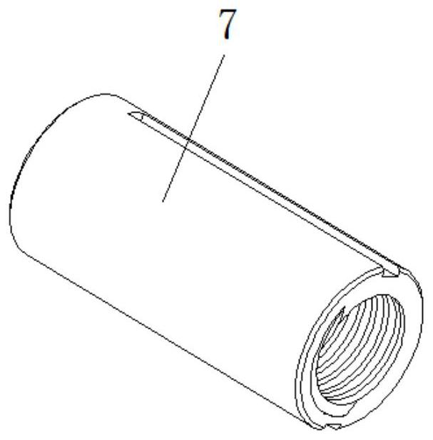
[0021] see Figure 1-4 , a reciprocating screw injection molding machine with controllable pressure, comprising a fixed bracket 1, a mold 2 is arranged inside the fixed bracket 1, a demoulding mechanism 3 is fixedly installed on one end of the mold 2, and a side outside the fixed bracket 1 is fixedly installed There is an injection barrel 4, and the mold 2 communicates with the inside of the injection barrel 4, a heating module 5 is provided on one side of the...


PUM


Abstract

The invention relates to the technical field of injection molding equipment, and discloses a reciprocating screw injection molding machine with controllable pressure, which includes a fixed bracket, a mold is arranged inside the fixed bracket, a demoulding mechanism is fixedly installed at one end of the mold, and a mold is fixed outside the fixed bracket. An injection barrel is fixedly installed on one side of the injection barrel, the mold communicates with the interior of the injection barrel, and a heating module is provided on one side of the outer surface of the injection barrel. The pressure-controllable reciprocating screw injection molding machine is set by pushing the slider and the rotating mandrel. When the driving device drives the rotating mandrel to rotate and shear the rubber, the injection machine is driven by the forward and backward movement of the pushing slider. The colloid in the inner cavity of the barrel is continuously squeezed into the mold. Compared with the existing screw injection molding machine, the colloid in the inner cavity of the injection machine barrel is pushed forward by pushing the slider, so that it will not cause The backflow of the colloid ensures that the colloid will not repeatedly stay inside the injection barrel and cause glue burning.

Description

technical field [0001] The invention relates to the technical field of injection molding equipment, in particular to a reciprocating screw injection molding machine with controllable pressure. Background technique [0002] The reciprocating screw injection molding machine is an injection-type plasticizing molding device that can move axially and rotate radially. Under the action of the screw rotation, the rubber material is strongly sheared, and the heating rate of the rubber material is increased. Faster, better uniformity of plasticization, no temperature gradient phenomenon in the rubber material, thereby improving the production efficiency of plasticization molding and the quality of plastic products. [0003] However, in the existing reciprocating screw injection molding machine, there is a gap between the peak of the screw and the inner wall of the barrel, which causes the colloid to form a countercurrent flow during injection, causing a part of the colloid to repeated...

Claims


Application Information

Patent Timeline
Patent Type & Authority Patents(China)
IPC IPC(8): B29C45/77B29C45/50
CPCB29C45/50B29C45/77B29C2945/76498
Inventor 田胜林
Owner 福建省东浦科技实业有限公司
Learn More