
Adjustable spiral oil press

An oil press and adjustable technology, applied in the field of mechanical processing, can solve the problems of wasting time and energy, unable to adjust the round ribs, affecting the efficiency of oil pressing, etc., to achieve the effect of improving efficiency

Active Publication Date: 2021-02-19
湖南亚美茶油股份有限公司
View PDF7 Cites 0 Cited by
  • Summary
  • Abstract
  • Description
  • Claims
  • Application Information

AI Technical Summary

Problems solved by technology

[0003] 1. The pressing cage of the screw oil press is fixed and installed as a whole, so it is impossible to adjust the pressing cage of some round ribs, so there are defects in the oil pressing of the same type of seeds with different drying degrees, which cannot be achieved. Good oil extraction effect. At the same time, it is impossible to adjust the gap between the round ribs to meet the required requirements when extracting oil from other seed materials. To achieve a good oil extraction effect, when the effect is poor, the slag still contains a large amount of oil and needs to be repeatedly pressed, wasting time and energy
[0004] 2. The interior of the oil press uses a spiral roller, and the screw gap of the screw shaft is getting smaller and smaller. In this way, a relatively dense slag layer is easily formed between the screw rod and the squeeze cage, so that it is easy to press the oil. The oil inside the cage gathers so that it cannot flow out, and it will also cause backflow, which will reduce the effect of pressing, and at the same time, it needs to be pressed many times to waste time, and it needs to be cleaned up for clogging, etc., which affects the pressing effect. oil efficiency

Method used


Image

  • Adjustable spiral oil press
  • Adjustable spiral oil press
  • Adjustable spiral oil press

Examples


Embodiment Construction

[0024] The following will clearly and completely describe the technical solutions in the embodiments of the present invention with reference to the accompanying drawings in the embodiments of the present invention. Obviously, the described embodiments are only some, not all, embodiments of the present invention. Based on the embodiments of the present invention, all other embodiments obtained by persons of ordinary skill in the art without making creative efforts belong to the protection scope of the present invention.

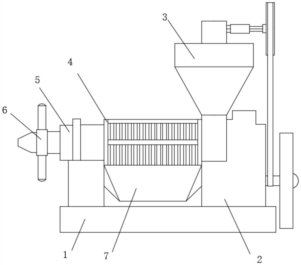
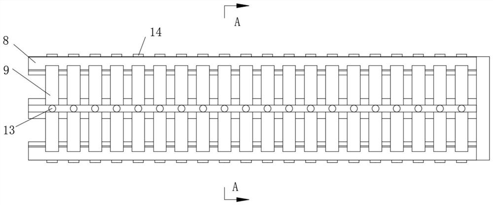
[0025] see Figure 1-8 , an adjustable screw oil press, comprising a base 1, a frame 5 is fixedly installed on the front of the top of the base 1, a gearbox 2 is fixedly installed on the back of the top of the base 1, a hopper 3 is fixedly installed on the top of the gearbox 2, the hopper A squeeze cage 4 is fixedly installed between the bottom of the frame 3 and the frame 5, a screw assembly 6 is installed on the front of the frame 5, an oil outlet groove 7 i...


PUM


Abstract

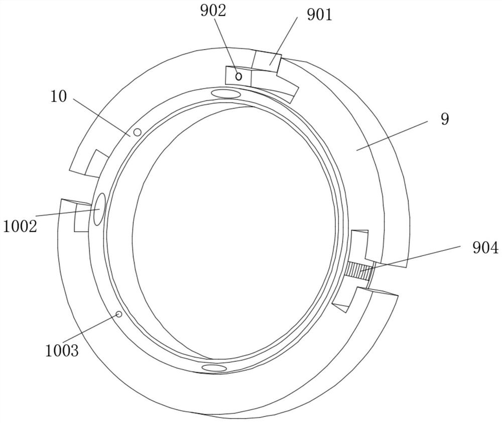
The invention relates to the technical field of machining, and discloses an adjustable spiral oil press. The adjustable spiral oil press comprises a base, wherein a machine frame is fixedly installedon the front face of the top of the base, a gearbox is fixedly installed on the back face of the top of the base, a hopper is fixedly installed on the top of the gearbox, and a pressing cage is fixedly installed between the bottom of the hopper and the machine frame; the pressing cage is composed of three fixing rods and a round rib, wherein the three fixing rods are fixedly installed at the bottom of the hopper in a triangular shape, the top of the fixing rod at the top end is sleeved with a fastening head in a threaded mode, the centers of the fixing rods on the two sides are movably sleevedwith fastening plugs, and clamping grooves are formed in the top and the two side of the round rib; and fastening holes are formed in the two side walls of the clamping grooves in the top, wherein spring blocks are movably mounted inside the fastening holes. According to the adjustable spiral oil press, gaps can be conveniently adjusted to adapt to oil pressing under different conditions in a sleeving mode through the round rib and the fixing rods, and meanwhile the oil pressing efficiency is not low according to movable rings.

Description

technical field [0001] The invention relates to the technical field of mechanical processing, in particular to an adjustable screw oil press. Background technique [0002] Edible oil is a kind of seasoning that is needed in daily life. It is basically extracted from plants. The method used is also the traditional pressing method, that is, the raw material seeds are pressed by an oil press to obtain an oil mixture, and then processed. Edible oil can be obtained. The common oil press is the screw oil press, which uses the screw to push the material and squeeze the oil. Its principle and structure are simple, but there are some problems that need to be solved during use: [0003] 1. The pressing cage of the screw oil press is fixed and installed as a whole, so it is impossible to adjust the pressing cage of some round ribs, so there are defects in the oil pressing of the same type of seeds with different drying degrees, which cannot be achieved. Good oil extraction effect. At ...

Claims


Application Information

Patent Timeline
Patent Type & Authority Applications(China)
IPC IPC(8): B30B9/12B30B15/00
CPCB30B9/12B30B15/00B30B15/0047
Inventor 张彬
Owner 湖南亚美茶油股份有限公司
Learn More