

Terminal and method of terminal shooting
A technology for terminals and shooting scenes, applied in the parts of color TVs, parts of TV systems, TVs, etc., can solve the problems of too high sensitivity ISO, amplifying noise, amplifying signals, etc.
- Summary
- Abstract
- Description
- Claims
- Application Information
AI Technical Summary
Problems solved by technology
Method used
Image

Examples
Embodiment 1
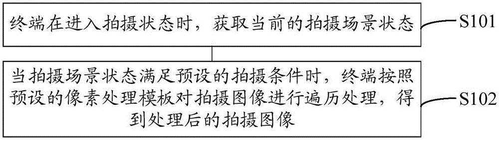
[0033] see figure 1 , which shows a method flow of a terminal shooting method provided by an embodiment of the present invention, the method may include:
[0034] S101: When the terminal enters the shooting mode, acquires the current shooting scene state;
[0035] Exemplarily, the terminal obtains the current state of the shooting scene, which may specifically include:
[0036] The terminal acquires the light intensity of the current shooting environment and / or the motion rate of the shooting object;
[0037] S102: When the state of the shooting scene satisfies the preset shooting condition, the terminal traverses the captured image according to the preset pixel processing template to obtain the processed captured image.
[0038] Exemplarily, it can be known from step S101 that the shooting scene state may include the light intensity of the current shooting environment, or may also include the light intensity of the current shooting environment and the motion rate of the sho...
Embodiment 2
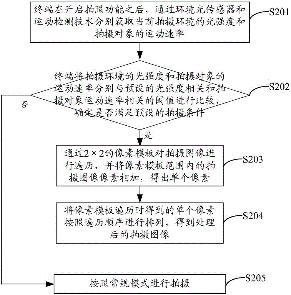
[0053] Based on the same technical idea of the foregoing embodiments, see figure 2 , which shows a detailed process of a terminal shooting method provided by an embodiment of the present invention, the process may include:
[0054] S201: After enabling the camera function, the terminal respectively obtains the light intensity of the current shooting environment and the motion rate of the shooting object through the ambient light sensor and the motion detection technology;
[0055] S202: The terminal compares the light intensity of the shooting environment and the motion speed of the shooting object with preset thresholds related to the light intensity and the motion speed of the shooting object, respectively, to determine whether the preset shooting conditions are met;
[0056] It should be noted that the preset thresholds related to the light intensity and the motion speed of the photographed object can be regarded as the shooting conditions proposed in the foregoing embod...
Embodiment 3
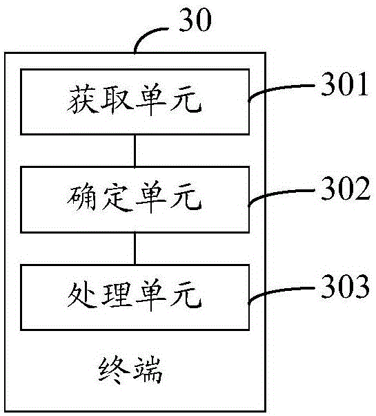
[0066] Based on the same technical idea of the foregoing embodiments, see image 3 , which shows the structure of a terminal 30 provided by an embodiment of the present invention, the terminal 30 may include: an acquisition unit 301, a determination unit 302, and a processing unit 303; wherein,
[0067] An acquisition unit 301, configured to acquire the current shooting scene state;
[0068] A determining unit 302, configured to determine whether the state of the shooting scene meets a preset shooting condition; and, when the state of the shooting scene meets the preset shooting condition, trigger the processing unit 303;
[0069] The processing unit 303 is configured to jointly process adjacent pixels in the captured image of the terminal according to a preset pixel processing strategy to obtain a processed captured image.
[0070] In the above solution, the state of the shooting scene includes the light intensity of the current shooting environment, or the light intensity...
PUM
 Abstract
Description
Claims
Application Information